Fluid ejecting apparatus and manufacturing method of fluid ejecting apparatus

a technology of fluid ejecting apparatus and manufacturing method, which is applied in the direction of metal-working apparatus, printing, writing implements, etc., can solve the problems of different liquid ejecting characteristics, and achieve the effect of improving the ejecting efficiency and reducing the ejecting ra

Inactive Publication Date: 2010-08-12
SEIKO EPSON CORP
View PDF6 Cites 9 Cited by
  • Summary
  • Abstract
  • Description
  • Claims
  • Application Information

AI Technical Summary

Benefits of technology

[0007]An advantage of some aspects of the invention is that it corrects a difference in density which occurs for each head.

Problems solved by technology

However, there are cases where these heads respectively have different liquid ejecting characteristics due to manufacturing error.

Method used


Image

  • Fluid ejecting apparatus and manufacturing method of fluid ejecting apparatus
  • Fluid ejecting apparatus and manufacturing method of fluid ejecting apparatus
  • Fluid ejecting apparatus and manufacturing method of fluid ejecting apparatus

Examples


embodiment

Description of Terms

[0045]First, the meaning of terms which are used in the description of this embodiment will be explained.

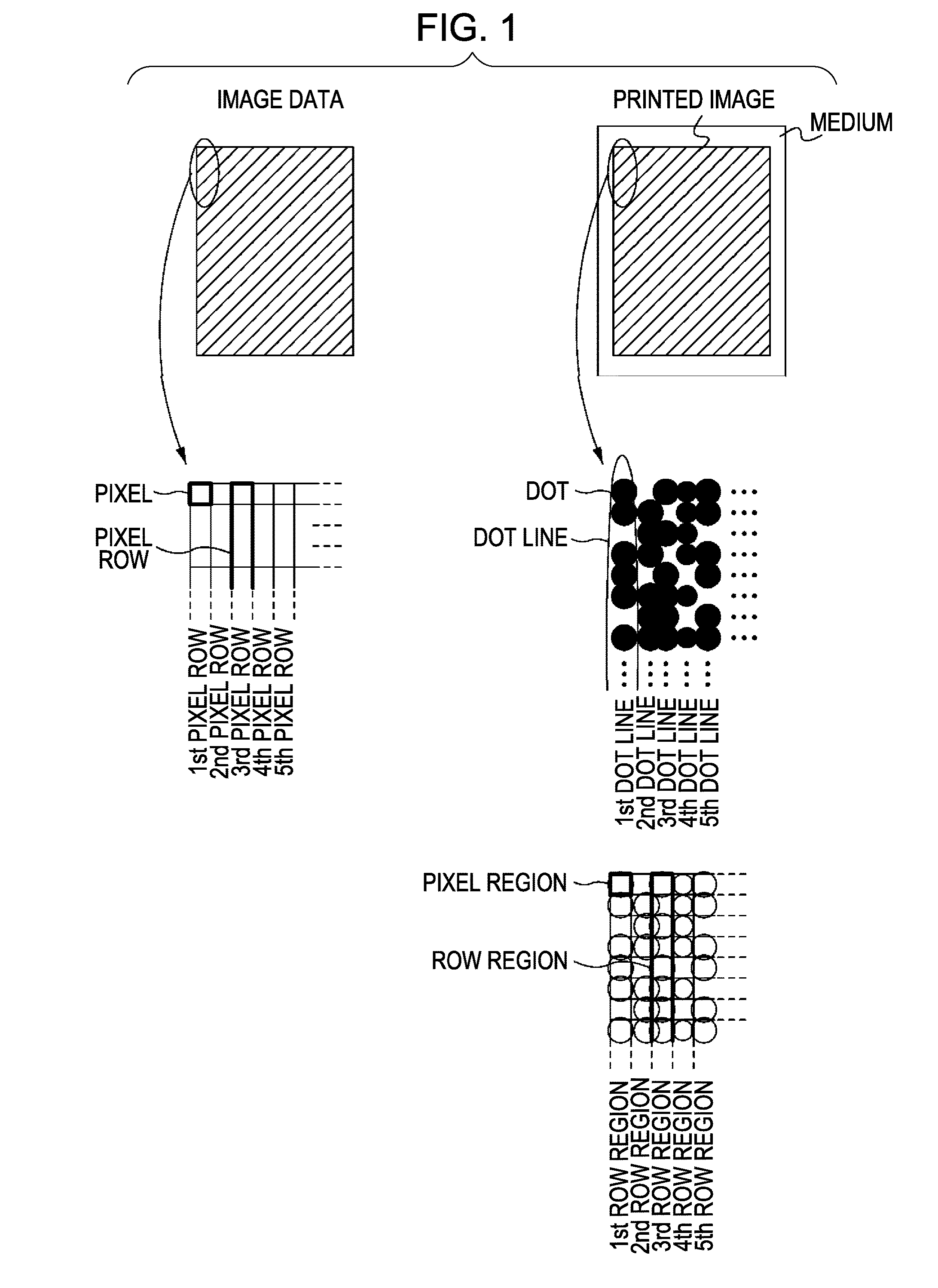
[0046]FIG. 1 is an explanatory view of terms.

[0047]The term “printed image” is an image printed on a piece of paper. A printed image of an ink jet printer is constituted of a countless number of dots formed on a piece of paper.

[0048]The term “dot line” is the row of dots arranged in a direction (movement direction) in which the head and the paper relatively move. In the case of a line printer as in an embodiment which will be described later, the “dot line” means the row of dots arranged in the transport direction of a piece of paper. On the other hand, in the case of a serial printer which performs printing by a head mounted on a carriage, the “dot line” means the row of dots arranged in the movement direction of the carriage. A number of dot lines are arranged in a direction perpendicular to the movement direction, so that a printed image is constituted. As ...


PUM

PropertyMeasurementUnit
Angleaaaaaaaaaa
Angleaaaaaaaaaa
Angleaaaaaaaaaa

Abstract

A manufacturing method of a fluid ejecting apparatus includes: forming first and second test patterns by ejecting fluid from first and second nozzle rows which intersect with a relative movement direction of a medium, wherein the first nozzle row forms the first test pattern by ejecting the fluid in accordance with a first driving pulse and the second nozzle row forms the second test pattern by ejecting the fluid in accordance with a second driving pulse; measuring the density of the first test pattern and the density of the second test pattern; and correcting a parameter of the first driving pulse and a parameter of the second driving pulse such that the density of the first test pattern and the density of the second test pattern become a common target density.

Description

BACKGROUND[0001]1. Technical Field[0002]The present invention relates to a manufacturing method of a fluid ejecting apparatus.[0003]2. Related Art[0004]A line type ink jet printer is considered which is provided with a plurality of heads disposed in a zigzag form and forms an image by ejecting liquid onto a medium which is transported. In such a printer, the heads are disposed such that adjacent heads partially overlap in the transport direction of the medium. The optimal driving voltages of the heads are different for every head, and they need to be determined for every head. A setting method of an optimal driving waveform is disclosed in JP-A-2006-240127.[0005]Another examples of the above-described related arts are disclosed in JP-A-2006-264069 and JP-A-2005-132034.[0006]In the line type ink jet printer as described above, a plurality of heads are arranged in a nozzle row direction. However, there are cases where these heads respectively have different liquid ejecting characteris...

Claims


Application Information

Patent Timeline
IPC IPC(8): B41J29/38B21D53/76
CPCB41J2/04508B41J2/04581B41J2/04588B41J2/0459Y10T29/49401B41J2/04596B41J29/38B41J29/393B41J2/04593
Inventor KONDO, TAKAMITSUTAKAHASHI, TORUMIYAMOTO, TORUKASAHARA, HIROKAZU
Owner SEIKO EPSON CORP
Why Eureka
Try Eureka