
Electromagnetic shock absorber for vehicle

Inactive Publication Date: 2010-08-12
TOYOTA JIDOSHA KK +2
View PDF8 Cites 29 Cited by
  • Summary
  • Abstract
  • Description
  • Claims
  • Application Information

AI Technical Summary

Benefits of technology

[0003]Some electromagnetic absorbers that employ the screw mechanism are equipped with a rotation inhibiting mechanism configured as follows. In order to efficiently convert a rotational force of one of a threaded rod and a nut into a force of the other of the threaded rod and the nut in its axis direction, the rotation inhibiting mechanism is configured to inhibit the other of the threaded rod and the nut from rotating about the axis. A rotational force about the axis acts on the rotation inhibiting mechanism when the absorber extends and contracts. When the extending or contracting movement of the absorber abruptly stops, such as upon full bounding and upon full rebounding, the rotational force that acts on the rotation inhibiting mechanism tends to become comparatively large due to the inertia or the like of the one of the threaded rod and the nut. Because the electromagnetic absorber that employs the screw mechanism is still under development, the absorber experiences various problems such as the large rotational force that acts on the rotation inhibiting mechanism and therefore, there is plenty of room for modification to improve the utility of the absorber. The present invention has been made in view of the situations described above. It is therefore an object of the invention to provide an electromagnetic absorber having a high degree of utility.

Problems solved by technology

Because the electromagnetic absorber that employs the screw mechanism is still under development, the absorber experiences various problems such as the large rotational force that acts on the rotation inhibiting mechanism and therefore, there is plenty of room for modification to improve the utility of the absorber.
Accordingly, in the absorber that employs the threaded rod in which the threaded groove is formed over the entirety of the outer circumferential portion in the axis direction, the fitting portion is inevitably fitted in a part of the axial groove at which the wall-less portions exist, so that only a part of the fitting portion suffers from a large load.

Method used


Image

  • Electromagnetic shock absorber for vehicle
  • Electromagnetic shock absorber for vehicle
  • Electromagnetic shock absorber for vehicle

Examples


first embodiment

1. First Embodiment

1-1. Construction of Electromagnetic Shock Absorber

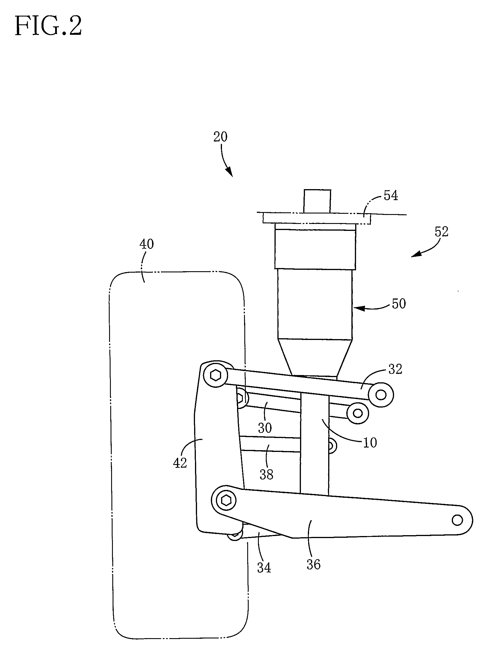
[0075]FIG. 1 shows a shock absorber 10 (hereinafter simply referred to as “absorber” where appropriate) for a vehicle according to a first embodiment of the claimable invention. The absorber 10 is installed on the vehicle as one constituent element of an independent suspension apparatus 20, as shown in FIG. 2, for instance. The suspension apparatus 20 of FIG. 2 is of a multilink type and includes a first upper arm 30, a second upper arm 32, a first lower arm 34, a second lower arm 36, and a toe control arm 38, each as a suspension arm. One end of each of these five arms 30, 32, 34, 36, 38 is rotatably connected to a body of the vehicle while the other end is rotatably connected to an axle carrier 42 that rotatably holds a wheel 40. Owing to the five arms 30, 32, 34, 36, 38, the axle carrier 42 is permitted to be vertically moved relative to the vehicle body along a substantially constant locus.

[0076]In the thus co...

second embodiment

2. Second Embodiment

[0101]FIG. 6 shows an electromagnetic shock absorber (hereinafter referred to as “absorber” where appropriate) 170 according to a second embodiment of the invention. The absorber 10 in the illustrated first embodiment is configured such that the spline nut 82 is fitted in the spline grooves 90 on one side of a portion of the threaded rod 78 where the nut 80 is screwed with the threaded rod 78, which one side is near to the proximal end portion of the threaded rod 78. In contrast, the absorber 170 in the second embodiment is configured such that a ball spline nut (hereinafter abbreviated as “spline nut” where appropriate) 172 is fitted in spline grooves 178 on one side of a portion of the threaded rod 174 where a nut 176 is screwed with the threaded rod 174, which one side is near to the leading end portion of the threaded rod 174. Except the above configuration, the absorber 170 in the second embodiment is substantially identical in construction with the absorber...


PUM


Abstract

An electromagnetic absorber (10) for a vehicle including (a) a threaded rod (78) which is disposed on one of a sprung portion and an unsprung portion and which has a threaded groove (76) formed in its outer circumferential portion and an axial groove (90) extending in its axis direction (b) a nut (80) which is rotatably disposed on the other of the sprung portion and the unsprung portion and which is screwed with the threaded rod and (c) a rod-rotation inhibiting member (82) which includes a fitting portion configured to be fitted in the axial groove and which is disposed on the other of the sprung portion and the unsprung portion, the rod-rotation inhibiting member being configured to inhibit the threaded rod from rotating while permitting the threaded rod to move in the axis direction. In the electromagnetic absorber, the threaded groove is not formed at a section of a fitting range at which the fitting portion is fitted in the axial groove when the fitting portion is located at an end of the fitting range that extends in the axis direction on the outer circumferential portion of the threaded rod.

Description

TECHNICAL FIELD[0001]The present invention relates to an electromagnetic shock absorber for a vehicle configured to generate, by an electromagnetic motor, a resistance force with respect to a relative movement of a sprung portion and an unsprung portion.BACKGROUND ART[0002]In the field of vehicles, there has been recently developed an electromagnetic shock absorber (hereinafter abbreviated as “absorber” where appropriate) configured to generate a resistance force with respect to a relative movement of a sprung portion and an unsprung portion, based on a force generated by an electromagnetic motor. An absorber disclosed in the following Patent Document 1 is one example of the electromagnetic absorber. The disclosed absorber employs a screw mechanism to convert a rotational force of the electromagnetic motor into the resistance force with respect to the relative movement of the sprung portion and the unsprung portion.[Patent Document 1] JP-A-2006-143146DISCLOSURE OF THE INVENTION(A) S...

Claims


Application Information

Patent Timeline
IPC IPC(8): F16F15/03
CPCB60G13/02F16F2232/06B60G15/10B60G17/02B60G2200/18B60G2202/12B60G2202/24B60G2202/314B60G2202/422B60G2204/128B60G2204/418B60G2204/419B60G2204/4502B60G2400/252B60G2500/30B60G15/065
Inventor KONDO, SATOSHIKONDO, TAKUHIROSHIGE, YOSHIFUMIKOYAGI, KATSURAWATANABE, HAJIME
Owner TOYOTA JIDOSHA KK
Learn More