
Bioactive carbon dioxide filter apparatus and method therefor

a carbon dioxide filter and carbon dioxide technology, applied in the field of emission control devices, can solve the problem of unidirectional flow of carbon dioxide gas through the device, and achieve the effect of reducing the level of carbon dioxid

Inactive Publication Date: 2010-07-29
JAGGI PARAM
View PDF2 Cites 12 Cited by
  • Summary
  • Abstract
  • Description
  • Claims
  • Application Information

AI Technical Summary

Benefits of technology

[0027]A primary purpose of the embodiments is to decrease the levels of carbon dioxide within the exhaust system of an internal combustion engine and other sources of carbon dioxide.
[0029]Another aspect of a preferred embodiment of the invention is the use of titanium and alloys of titanium in construction of the canister cartridge and filter elements. The heat transfer characteristics of titanium and titanium alloys assist in conducting heat away from the sensitive biological elements contained. Furthermore, mechanical heat sinks constructed of titanium and titanium alloy on the interior and exterior of the canister increase both convective and radioactive heat transfer properties in a favorable way.
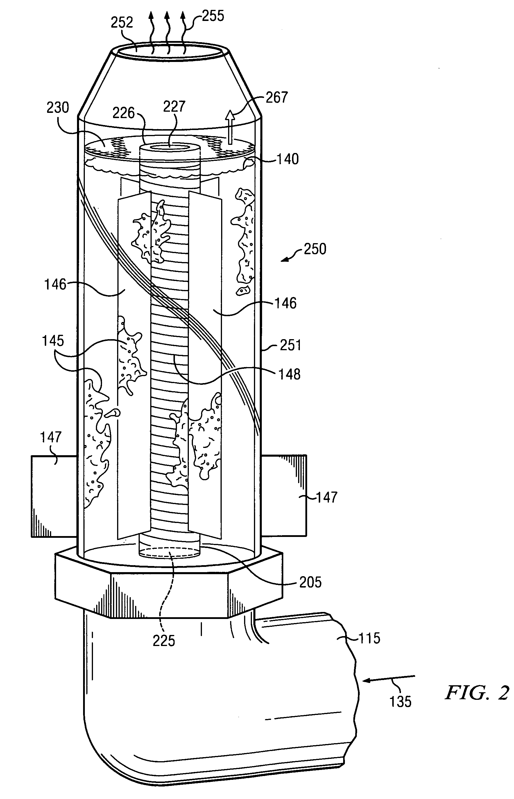
[0030]Another aspect of the device is the unidirectional flow of the carbon dioxide gas through the device. Tubes and surrounding filter parts are designed to create an optimal condition for the algae. The device prevents return exhaust flow into the passenger compartment or engine components. The device prevents sudden malfunction of the engine and the surrounding parts. The device allows vastly reduced flow restriction allowing more efficient and stable bio reaction and carbon dioxide decontamination.
[0033]An important aspect of the device is to preserve algae viability. The algae must be maintained at a non-lethal temperature despite the heat from the exhaust gases and surrounding components. To cool the algae when the device is in use, mechanical heat sinks both internal and external to the canister are provided. To keep the algae warm, a coat of insulation surrounds the device to sustain the algae in extreme temperatures.
[0034]Another aspect of the device is the configuration of the algae within the device. In one embodiment, algae must be kept at or near the center of the device in order to maximize the protection of the insulation. Additionally, when placing the initial colony of algae within the device, sufficient space must be left within the device to account for algae growth. Where environmental conditions permit, algae may be attached to the inner walls of the algae filter, as well as any structures within the filter. The structures are designed to center the algae within the device thereby allowing it free access to nutrients and light energy.

Problems solved by technology

Another aspect of the device is the unidirectional flow of the carbon dioxide gas through the device.

Method used


Image

  • Bioactive carbon dioxide filter apparatus and method therefor
  • Bioactive carbon dioxide filter apparatus and method therefor
  • Bioactive carbon dioxide filter apparatus and method therefor

Examples


Embodiment Construction

[0042]This invention may be embodied in many different forms and should not be construed as limited to the embodiments described. The embodiments are provided by way of example.

[0043]The first aspect of the design, which is imperative to the conversion of the carbon dioxide into oxygen, is the algae and fluid within the canister. The algae are grown in a glass container which is 51×24.5×29 cm and is grown for approximately 4-6 weeks for optimal production of oxygen. The algae are kept in optimal conditions to increase reproduction within the colonies. The procedure for growing the algae will be described later.

[0044]In order to create a living colony of algae, a tank is filled with water and placed outside in the sunlight. It is preferable for the tanks to be clear on all sides in order to allow the maximum amount of sunlight into the tank and promote photosynthesis within the algae. It may be necessary to condition the water for algae growth depending on the source of the water. Fo...


PUM

PropertyMeasurementUnit
transparentaaaaaaaaaa
partial chargeaaaaaaaaaa
electricalaaaaaaaaaa

Abstract

A bioactive filter is provided which comprises a transparent canister having gas permeable membranes as entry and exit ports. A source of carbon dioxide in gaseous form is allowed to enter the entry membrane and pass through a solution contained in the canister which supports a live colony of algae. The algae carries out photosynthesis thereby altering the carbon dioxide to oxygen and sugar. The oxygen is released through the exit port.

Description

CROSS-REFERENCE TO RELATED APPLICATIONS[0001]This application claims priority to U.S. Provisional Application No. 61 / 203,564, entitled “Creating An Anti-Pollutant Device Based Upon Algae and Enzymes,” filed Dec. 23, 2008.TECHNICAL FIELD OF THE INVENTION[0002]The present invention relates to emission control devices. More specifically, the invention relates to devices that reduce the level of gaseous carbon exhaust products resulting from combustion engines. Gaseous carbon dioxide is converted into oxygen through a photosynthesis process carried out by algae encapsulated within a canister used as a filter in the exhaust stream.BACKGROUND OF THE INVENTION[0003]The world faces various problems of global warming and pollution that has brought disparity to societies across the world. Global warming has caused damage in all parts of our society from the fluctuation of weather to affecting the lifestyles of common animals. Humans have created an environment that has become accustomed to mo...

Claims


Application Information

Patent Timeline
Patent Type & Authority Applications(United States)
IPC IPC(8): B01D53/84B01D53/34B01D53/62
CPCB01D53/62B01D53/84B01D2251/95B01D2256/12B01D2257/504B01D2258/01Y02C10/04C12M21/02C12M23/24C12M25/06C12M29/22C12N1/12Y02C10/02B01D2259/802Y02P20/59Y02P60/20Y02A50/20Y02C20/40
Inventor JAGGI, PARAM
Owner JAGGI PARAM
Learn More