
Driving method for liquid crystal display device and related device

a liquid crystal display and driving method technology, applied in the direction of electric digital data processing, instruments, computing, etc., can solve the problems of deteriorating image quality, more power consumption, and inability to accurately polarize or refraction incident light,

Active Publication Date: 2010-07-29
NOVATEK MICROELECTRONICS CORP
View PDF32 Cites 33 Cited by
  • Summary
  • Abstract
  • Description
  • Claims
  • Application Information

AI Technical Summary

Benefits of technology

[0017]The present invention further discloses a liquid crystal display (LCD) device. The LCD device comprises a display panel, a timing controller, a charge sharing module, and a source driver. The timing controller is used for outputting an LD signal and a polarity signal. The charge sharing module is coupled to the timing controller and used for detecting a driving approach of the LCD to output a control signal according to the LD signal and the polarity signal. The source driver is coupled to the display panel and the charge sharing module and used for outputting image data to the display panel and adjusting a coupling relationship among a plurality of data channels to correct charge sharing performed on the plurality of data channels according to the control signal.

Problems solved by technology

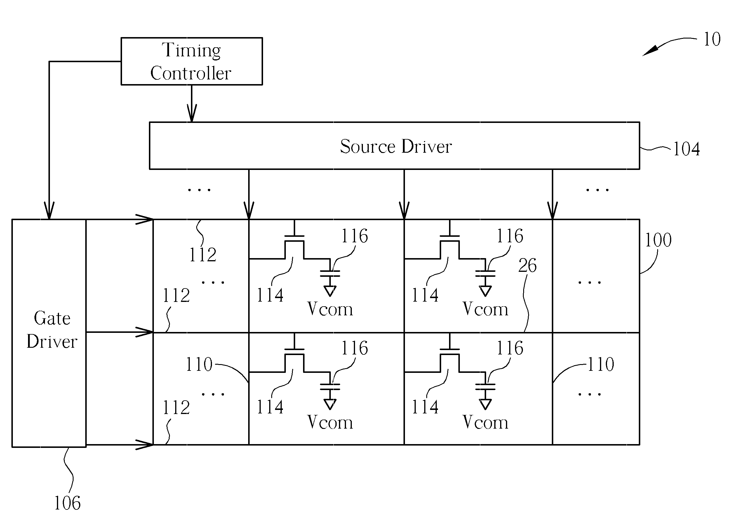
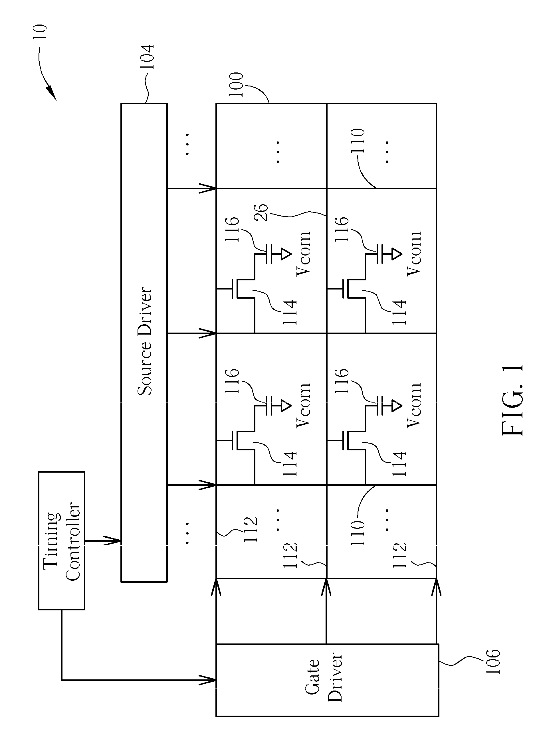
Thus, the incident light will not produce accurate polarization or refraction, and the quality of images displayed on the LCD device 10 deteriorates.
Consequently, more power consumption will be caused if the polarity must remain positive.
In other words, charge sharing does not save power, but causes even greater power consumption.
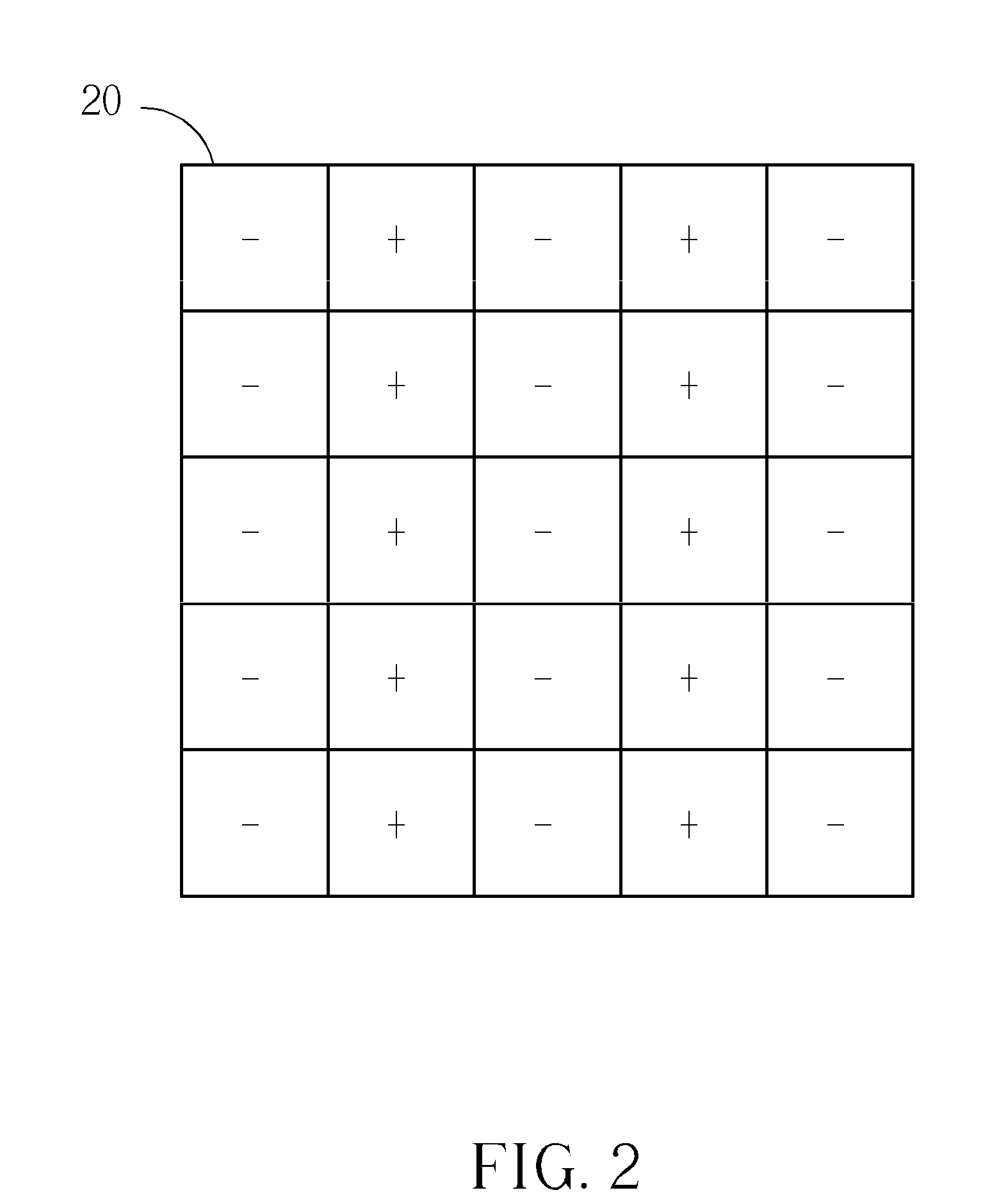
As shown above, charge sharing cannot be adapted to all kinds of driving approaches according to the prior art; for example, in column inversion driving approach, extra power consumption may be caused.

Method used


Image

  • Driving method for liquid crystal display device and related device
  • Driving method for liquid crystal display device and related device
  • Driving method for liquid crystal display device and related device

Examples


Embodiment Construction

[0030]Please refer to FIG. 8, which is a schematic diagram of an LCD device 80 according to an embodiment of the present invention. The LCD device 80 may be driven by a dot inversion driving approach or a column inversion driving approach. The LCD device 80 includes a display panel 800, a timing controller 802, a source driver 804, a gate driver 806, and a charge sharing module 808. The structure of the LCD device 80 is similar to the LCD device 10 and thus identical parts thereof are not elaborated on herein. The difference is that the charge sharing module 808 can determine a driving approach of the LCD device to perform charge sharing accordingly, and further reduce power consumption by reusing electrical charges. To realize the operations mentioned above, as shown in FIG. 9, the source driver 804 includes a plurality of amplifiers AMP_1˜AMP_n and a switch module 900. The amplifiers AMP_1˜AMP_n are exploited to transmit driving signals toward corresponding data lines with respect...


PUM


Abstract

A driving method for a Liquid Crystal Display (LCD) device is used for reducing power consumption of the LCD device. The driving method includes determining a driving approach of the LCD device, and performing corresponding charge sharing on a plurality of data channels according to the driving approach. The driving approach of the LCD device is determined according to a latch data (LD) signal and a polarity signal.

Description

BACKGROUND OF THE INVENTION[0001]1. Field of the Invention[0002]The present invention relates to a driving method for a liquid crystal display (LCD) device and a related device, and more particularly, to a driving method of performing corresponding charge sharing according to a driving approach of the LCD, and a related device.[0003]2. Description of the Prior Art[0004]The advantages of a liquid crystal display (LCD) include lighter weight, less electrical consumption, and less radiation contamination as compared to other conventional displays. Thus, LCD devices have been widely applied to various portable information products, such as notebooks, PDAs, etc. In an LCD device, incident light produces different polarization or refraction effects when the alignment of liquid crystal molecules is altered. The transmission of the incident light is affected by the liquid crystal molecules, and thus magnitude of the light emitting out of the liquid crystal molecules varies. The LCD device u...

Claims


Application Information

Patent Timeline
IPC IPC(8): G09G5/00
CPCG09G3/3614G09G2330/021G09G3/3688G09G3/3685G09G5/18
Inventor CHEN, JI-TINGSUNG, KUANG-FENG
Owner NOVATEK MICROELECTRONICS CORP
Learn More