
Biomechanically derived crutch

Active Publication Date: 2010-07-29
MOBI
View PDF34 Cites 4 Cited by
  • Summary
  • Abstract
  • Description
  • Claims
  • Application Information

AI Technical Summary

Benefits of technology

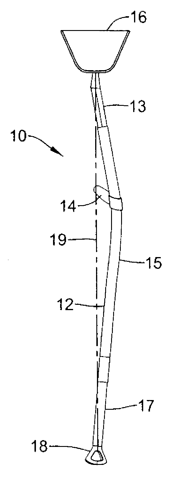
[0005]One embodiment pertains to an arcuate crutch having a mesh saddle disposed on a curved leg. The saddle includes a resilient mesh web disposed over a frame pivotably attached to the leg. The frame may flex with the weight of the user to spread outwards and provide greater contact area with the user and to help the saddle stay with the user during use. The leg may be curved outwardly to accommodate the shape of the user while maintaining a narrow footprint and curved to the front to properly position the handle. The leg may be adjustable and may include two or three sections which slide with respect to each other to accommodate users of various heights. The handle may be fixed to the leg and may extend back from the frame at an upward and outward angle to provide a natural and ergonomic position for the hand. The foot may include an oval, curved tread pattern and may flex to provide cushioning and orientation.

Problems solved by technology

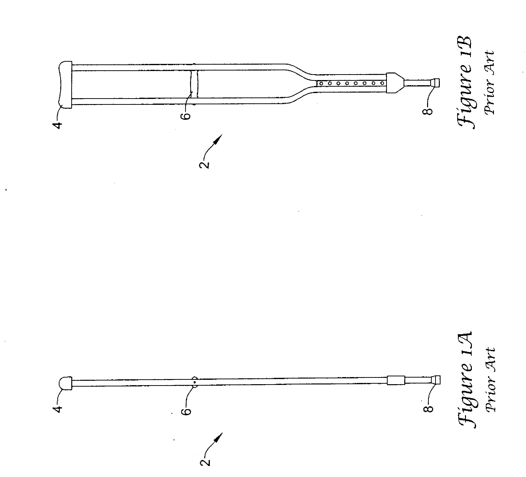
The crutch handle is a narrow tube disposed horizontally in a narrow opening and this creates soreness in the hand and wrist.
The crutch foot 8 generally widens at the bottom and so catches under doors and ledges, making use more difficult.
This crutch typically has a low degree of adjustability, which requires many sizes to be stocked to accommodate the variety of sizes found in the population.

Method used


Image

  • Biomechanically derived crutch
  • Biomechanically derived crutch
  • Biomechanically derived crutch

Examples


Embodiment Construction

[0029]An example crutch 10, shown in front and side views in FIGS. 3A and 3B respectively, includes an elongate leg 12 having a handle 14 disposed thereon and has a saddle 16 at the top and a foot 18 at the bottom. Crutch 10 is a handed crutch and is configured for optimal use with a particular hand and side of the body. The particular crutch 20 shown is a left-handed crutch, but references to crutch 10 should not be understood as limited to a crutch of a particular handedness. A right-handed crutch is omitted for the sake of simplicity, but it should be understood that the discussion herein is applicable to right-handed crutches, which are contemplated and which are in a mirror image of their left-handed counterparts. Further, it is anticipated that the crutches disclosed herein may and often will be packaged in a set including a left-handed crutch and a right-handed crutch. Still further, some embodiments and features of the present invention are not limited to handed crutch and m...


PUM


Abstract

A crutch having a first side direction, a second side direction opposite the first side direction, a third side direction perpendicular to the first side direction and a fourth side direction opposite the third side direction, the crutch including an elongate leg having a top end, a top portion, a middle portion, a bottom portion, and a bottom end, wherein the elongate leg extends from a saddle to a foot and has a handle disposed on the middle portion, wherein the saddle extends in an elongate shape between the first side direction and the second side direction, wherein the handle extends in an elongate shape between the first side direction and the second side direction, wherein the elongate leg middle portion is to the third side direction of an axis extending between the leg and the foot, wherein the elongate leg middle portion is to the first side direction of an axis extending between the top end of the elongate leg and the bottom end of the elongate leg; and wherein the handle is cantilevered and has a fixed end and a free end.

Description

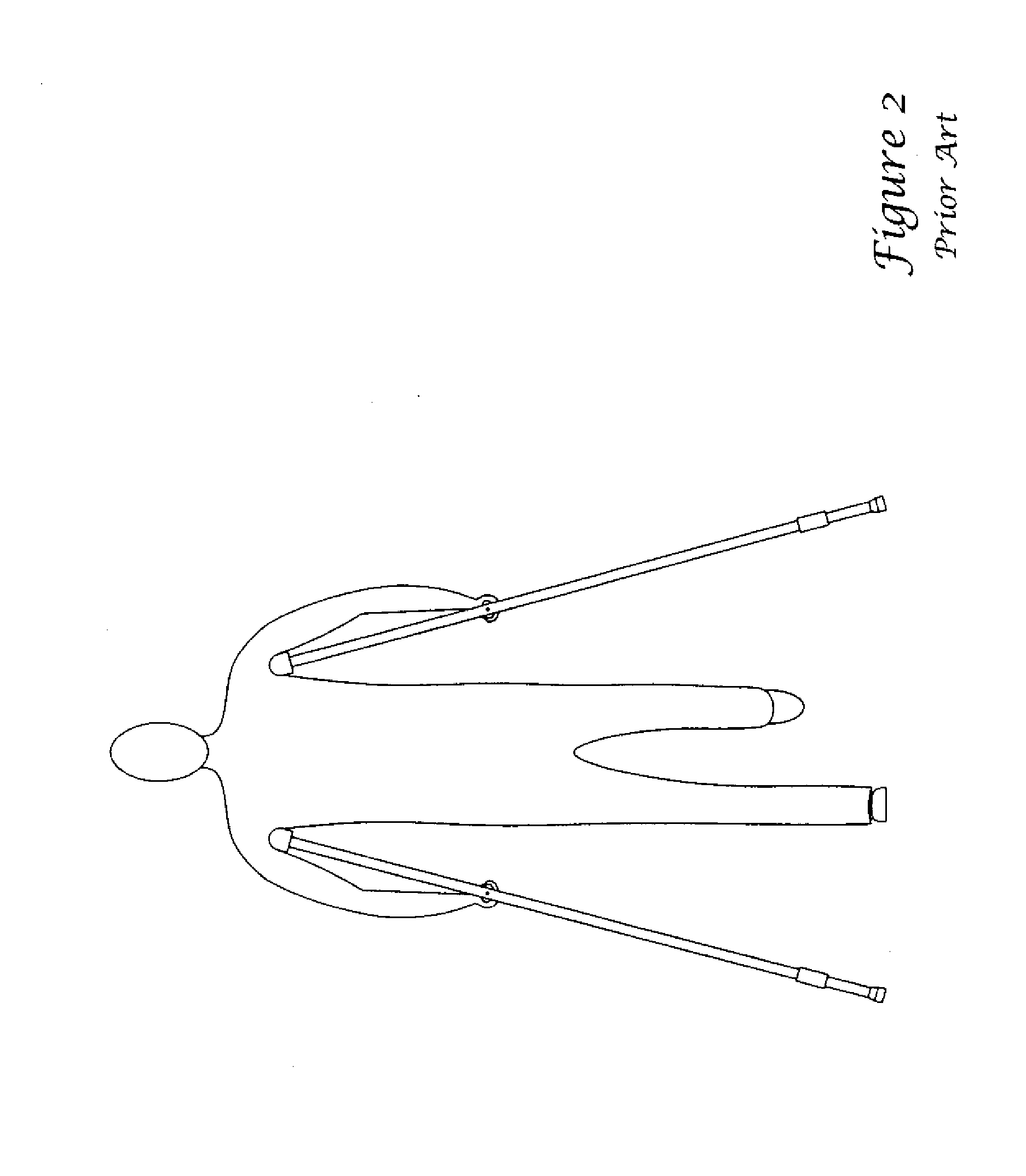
RELATED APPLICATIONS[0001]This application is a continuation of U.S. patent application Ser. No. 11 / 621,893, filed Jan. 10, 2007.FIELD[0002]This invention pertains to medical devices for ambulatory assistance such as crutches and more particularly to improvements to the ergonomics and ease-of-use of crutches.BACKGROUND[0003]Crutches are used by millions of people each year recovering from lower-limb ailments such as broken bones, knee injuries and sprained ankles. One of the most common crutches in use today is some variation of that shown in FIGS. 1A and 1B. This crutch 2 has a saddle 4 generally covered by a foam rubber pad, which is hot, sticky and causes under-arm skin abrasion. The crutch has a narrow transverse handle 6 that puts undo strain on the wrist by forcing it into a collapsed position. The crutch handle is a narrow tube disposed horizontally in a narrow opening and this creates soreness in the hand and wrist. The crutch foot 8 generally widens at the bottom and so cat...

Claims


Application Information

Patent Timeline
IPC IPC(8): A61H3/02
CPCA61H3/02A61H2003/0205A61H2201/1635A61H2003/0216A61H3/0277
Inventor WEBER, JEFFREY A.MONITOR, SHAWNGRIDER, MICHAEL
Owner MOBI
Learn More