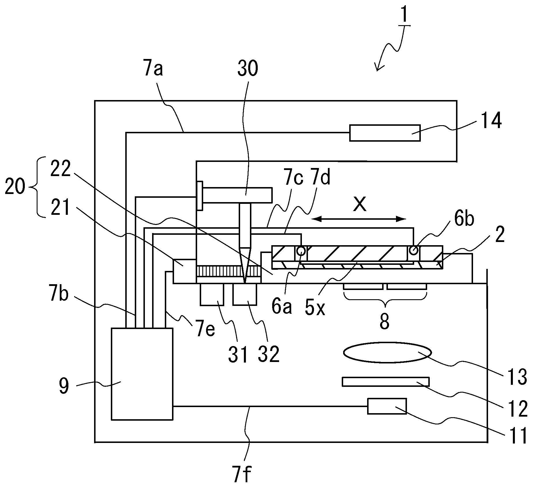
Analysis apparatus for capillary electrophoresis
an analysis apparatus and electrophoresis technology, applied in the direction of diaphragms, sludge treatment, peptides, etc., can solve the problems of low hemoglobin a1c measurement accuracy, low specificity of affinity chromatography methods, lack of measurement accuracy of immunological methods and enzymatic methods, etc., to achieve rapid and accurate analysis of samples, reduce size, and analyze samples quickly and accurately
- Summary
- Abstract
- Description
- Claims
- Application Information
AI Technical Summary
Benefits of technology
Problems solved by technology
Method used
Image
Examples
example 1
[0077]An electrophoresis chip used for the capillary electrophoresis analysis apparatus for Example 1 is shown in FIG. 1. FIG. 1 (A) is a planar view of the electrophoresis chip. FIG. 1 (B) is a cross-sectional view along the direction of line I-I of the electrophoresis chip shown in FIG. 1 (A). FIG. 1 is a schematic diagram for easier understanding. Accordingly, the size, proportions and features of each component are not intended to be limiting. As shown in FIG. 1, the electrophoresis chip 2 includes a lower substrate 3b and an upper substrate 3a, and the upper substrate 3a is laminated onto the lower substrate 3b. Three through-holes are formed in the upper substrate 3a. The bottom parts of the three through-holes of the upper substrate 3a are sealed with the lower substrate 3b by laminating the upper substrate 3a onto the lower substrate 3b, and three concave portions are formed thereby in the electrophoresis chip 2. They serve as liquid reservoirs 4a, 4b, and 4e, respectively. ...
example 2
[0092]An electrophoresis chip used for the capillary electrophoresis analysis apparatus of Example 2 is shown in FIG. 3. In FIG. 3, the features that are identical to those in FIG. 1 are given the same numbers and symbols. FIG. 3 (A) is a planar view of the electrophoresis chip, FIG. 3 (B) is a cross-sectional view viewed along the direction of line I-I of the electrophoresis chip shown in FIG. 3 (A), and FIG. 3 (C) is a cross-sectional view viewed along the direction of line II-II of the electrophoresis chip shown in FIG. 3 (A). FIG. 3 is a schematic diagram for ease of understanding, but the size, proportions and like features of each component are not limited thereto.
[0093]As shown in FIG. 3, the electrophoresis chip 2 is composed of a lower substrate 3b and an upper substrate 3a, the upper substrate 3a being laminated onto the lower substrate 3b. A plurality of through-holes (four in this example) are formed in the upper substrate 3a. The bottom parts of the four through-holes f...
example 3
[0102]An electrophoresis chip used for the capillary electrophoresis analysis apparatus of Example 3 is shown in FIG. 4. In FIG. 4, the portions that are identical to those in FIG. 1 and FIG. 3 are given the same numbers and symbols. FIG. 4 (A) is a planar view of the electrophoresis chip, and FIG. 4 (B) is a perspective view of the electrophoresis chip. FIG. 4 is a schematic diagram for easier understanding, and the size, proportions and like features of each component are not limited thereto and may be different therefrom. As shown in FIG. 4, the electrophoresis chip 200 includes a lower substrate 3b, an upper substrate 3a, and a connector 70. The connector 70 is arranged on a side surface of a laminated body in which the upper substrate 3a is laminated onto the lower substrate 3b. A wiring pattern (not shown) is formed on the lower substrate 3b.
[0103]Six through-holes are formed in the upper substrate 3a. The bottom parts of the six through-holes are sealed with the lower substr...
PUM
| Property | Measurement | Unit |
|---|---|---|
| height | aaaaa | aaaaa |
| depth | aaaaa | aaaaa |
| thickness | aaaaa | aaaaa |
Abstract
Description
Claims
Application Information
 - R&D
- Intellectual Property
- Life Sciences
- Materials
- Tech Scout
- Unparalleled Data Quality
- Higher Quality Content
- 60% Fewer Hallucinations
Browse by: Latest US Patents, China's latest patents, Technical Efficacy Thesaurus, Application Domain, Technology Topic, Popular Technical Reports.
© 2025 PatSnap. All rights reserved.Legal|Privacy policy|Modern Slavery Act Transparency Statement|Sitemap|About US| Contact US: help@patsnap.com


