Bus access control apparatus and method

Inactive Publication Date: 2010-07-15
IBM CORP
View PDF15 Cites 9 Cited by
  • Summary
  • Abstract
  • Description
  • Claims
  • Application Information

AI Technical Summary

Benefits of technology

[0014]According to the present invention, bus access is allocated to each IP core according to a predetermined schedule and therefore a bus band available

Problems solved by technology

The above system where multiple IP cores share the bus as described above was unable to explicitly ensure hard real-time accessibility and bus-band availability.
Another pr

Method used


Image

  • Bus access control apparatus and method
  • Bus access control apparatus and method
  • Bus access control apparatus and method

Examples


Example

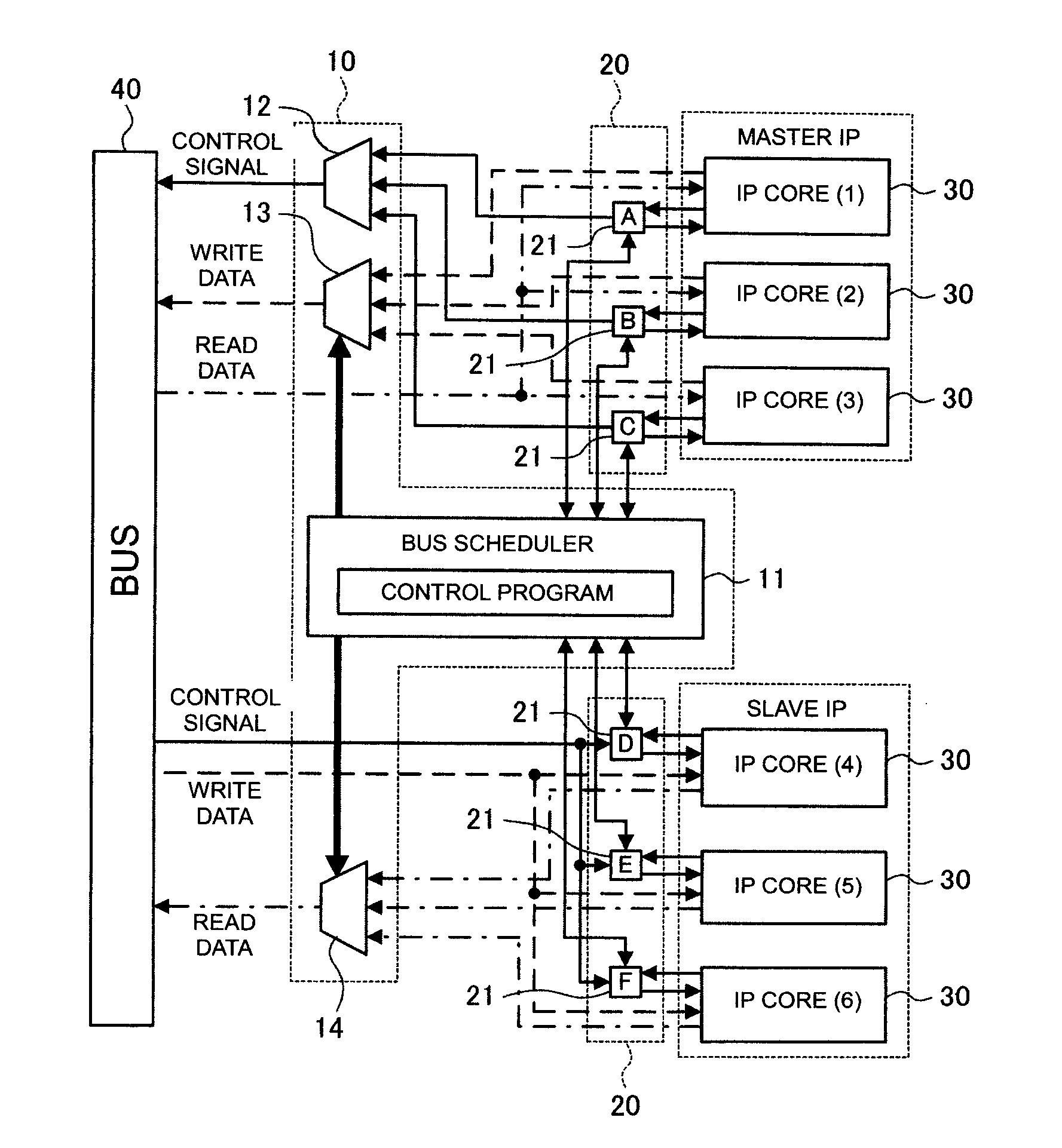
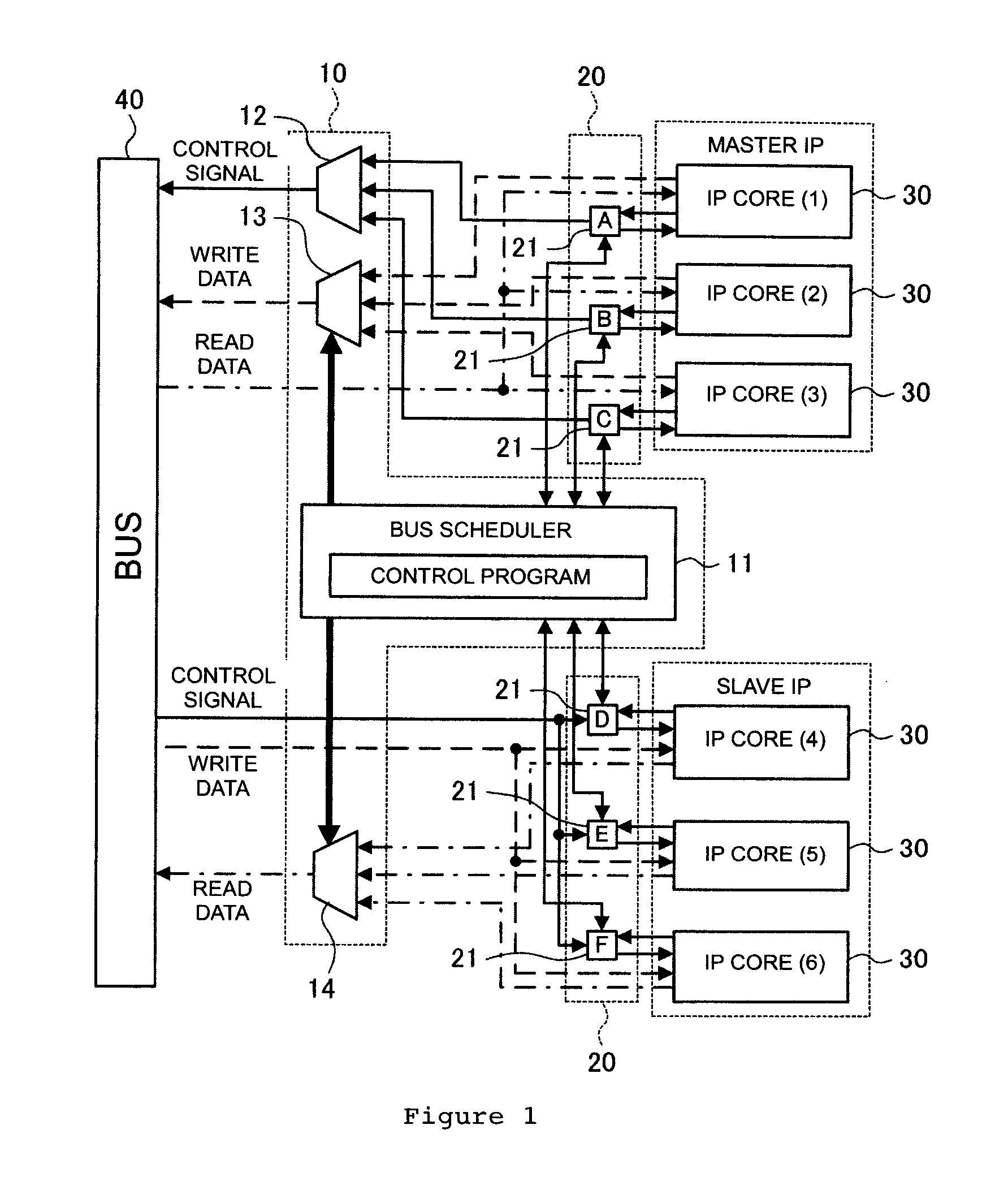
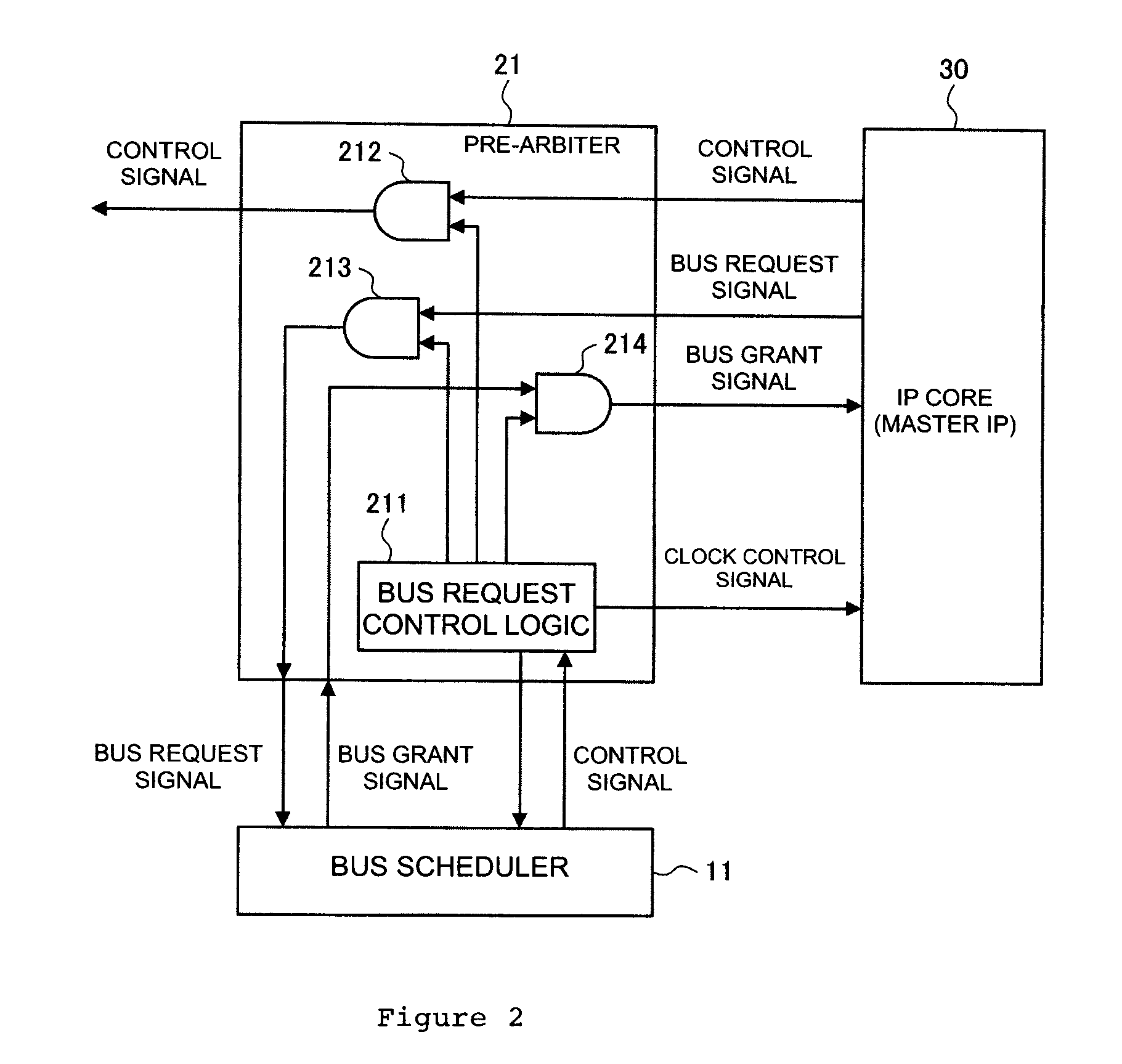
[0022]Representation of various reference numerals used in the drawings are summarized as in below:[0023]10 . . . Main controller,[0024]11 . . . Bus scheduler,[0025]12, 13, 14 . . . Multiplexer,[0026]20 . . . Sub controller,[0027]21 . . . Pre-arbiter,[0028]30 . . . IP core,[0029]40 . . . Bus

DETAILED DESCRIPTION OF EMBODIMENTS

[0030]Embodiments of the present invention will be described below in detail with reference to the accompanying drawings.

[0031]FIG. 1 illustrates an exemplary configuration of a bus control system to which an embodiment of the present invention is applied.

[0032]As illustrated in FIG. 1, the bus control system of the present embodiment includes a main controller 10 which allocates access to a bus 40 and a sub controller 20 which controls access by IP cores 30 to the bus 40 under the control of the main controller 10. In the example illustrated in FIG. 1, six IP cores 30 share the bus. In the following description, when the individual cores 30 need to be distingui...


PUM


Abstract

An apparatus that controls access by multiple IP cores to a bus is provided. The apparatus includes a main controller and multiple sub controllers, each of the sub controllers being associated with each IP cores. The main controller switches connection between each of the IP cores and the bus according to a schedule predetermined based on predetermined time slices. Each of the sub controllers controls access by the IP core to the bus according to a schedule under the control of the main controller. Embodiments of the present invention provide method and apparatus to ensure real-time accessibility to a bus shared by multiple IP cores and improve bus use efficiency.

Description

CROSS-REFERENCE TO RELATED APPLICATION[0001]The present application claims the benefit of priority of a Japanese Patent Application No. 2009-6827, filed Jan. 15, 2009 with the Japan Patent Office, the content of which is incorporated herein by reference in its entirety.FIELD OF THE INVENTION[0002]The present invention relates to an apparatus and a method for controlling bus access in a system in which multiple IP cores share a bus.BACKGROUND OF THE INVENTION[0003]In a system in which a bus such as a system bus is shared by multiple devices (IP cores), a controller (bus arbiter) allocates access to the bus among the IP cores. Each IP core requests access to the bus through the controller. Whenever the controller receives a request from an IP core, the controller arbitrates among the IP cores to allocate access to the bus to the IP core according to a preset rule such as priority given to each IP core.[0004]FIG. 7 schematically illustrates a configuration of a bus control system of th...

Claims


Application Information

Patent Timeline
IPC IPC(8): G06F13/00
CPCG06F13/366G06F13/364
Inventor MATSUSE, SHUHSAKU
Owner IBM CORP
Why Eureka
Try Eureka