
Stimulation leads, delivery systems and methods of use

a technology of stimulation leads and delivery systems, applied in the field of stimulation leads, can solve problems such as insufficient stimulation, and achieve the effects of minimizing possible complications and side effects, minimizing or excluding undesired neuromodulation, and minimizing or excluding unwanted side effects

Inactive Publication Date: 2010-07-15
ST JUDE MEDICAL LUXEMBOURG HLDG SMI S A R L SJM LUX SMI
View PDF103 Cites 194 Cited by
  • Summary
  • Abstract
  • Description
  • Claims
  • Application Information

AI Technical Summary

Benefits of technology

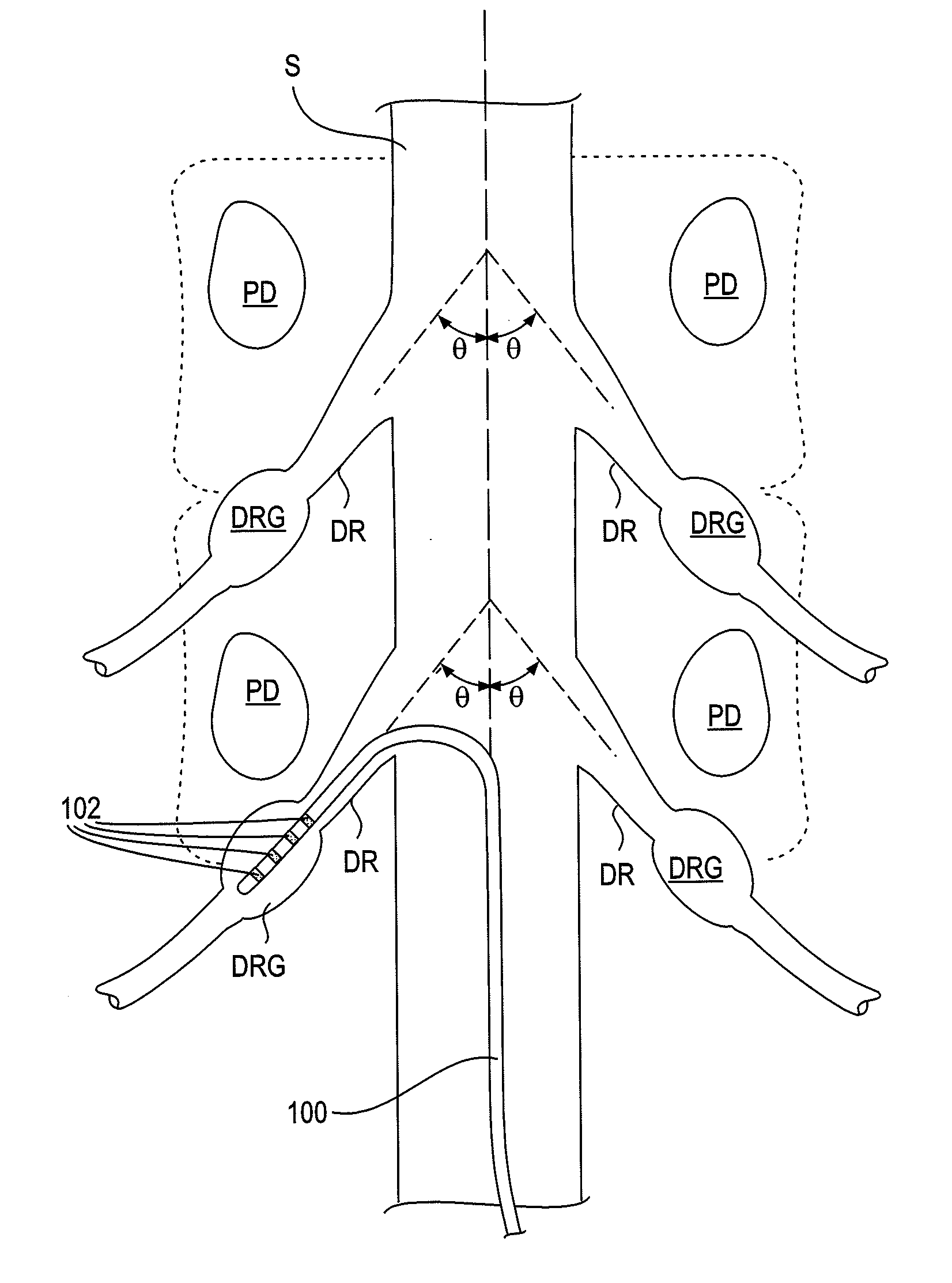
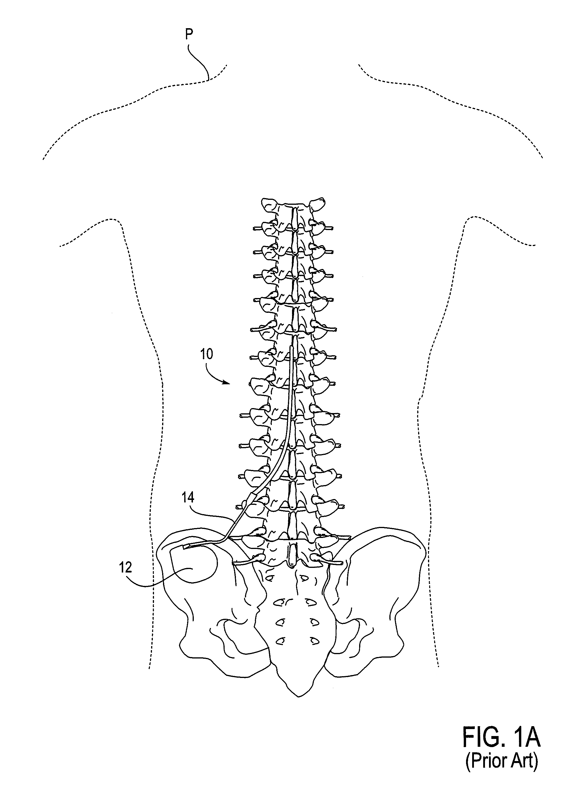
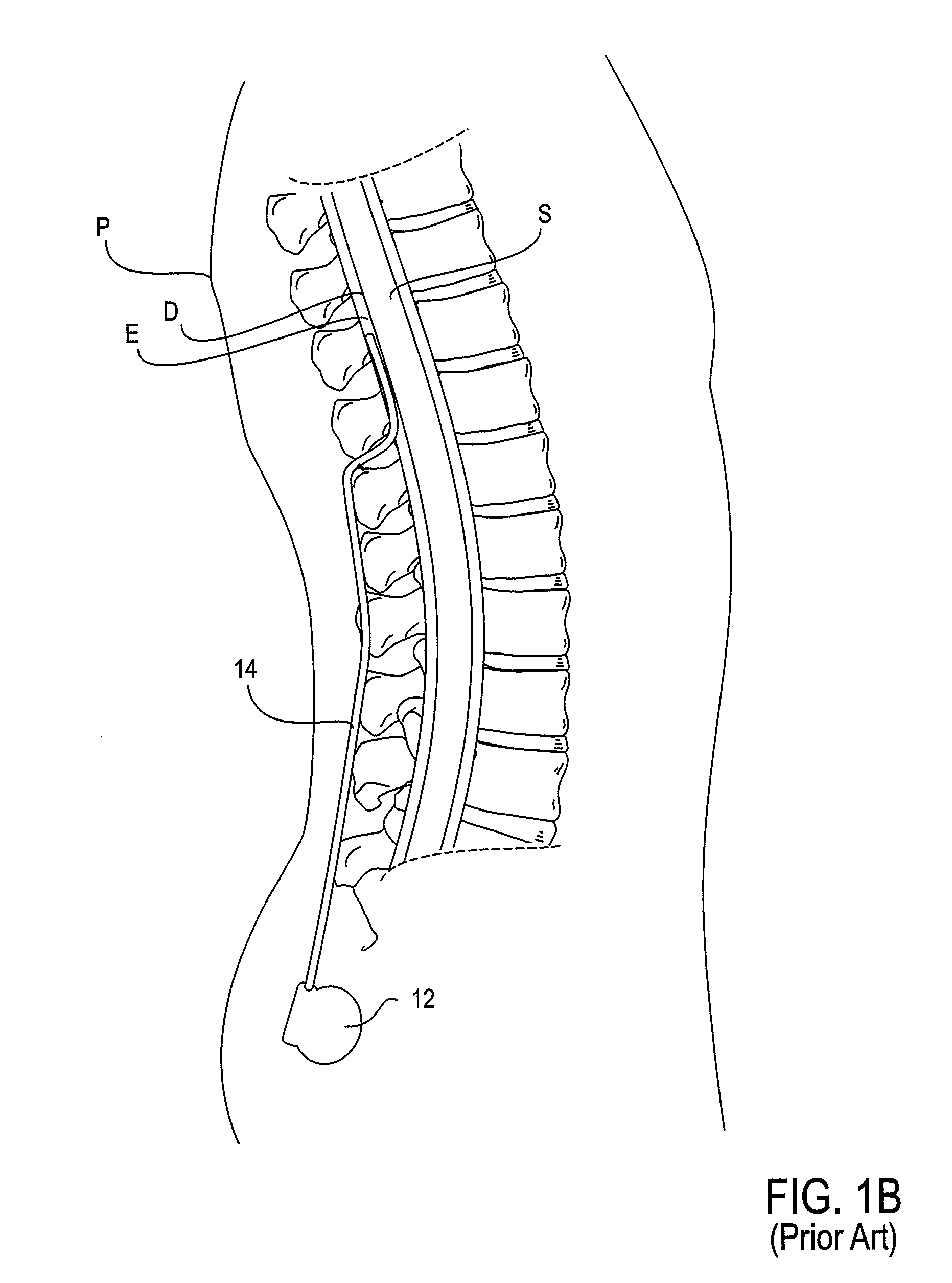
[0011]The present invention provides devices, systems and methods for accessing and treating anatomies associated with a variety of conditions while minimizing possible complications and side effects. This is achieved by directly neuromodulating a target anatomy associated with the condition while minimizing or excluding undesired neuromodulation of other anatomies. Typically, this involves stimulating portions of neural tissue of the central nervous system, wherein the central nervous system includes the spinal cord and the pairs of nerves along the spinal cord which are known as spinal nerves. In particular, some embodiments of the present invention are used to selectively stimulate portions of the spinal nerves, particularly one or more dorsal root ganglions (DRGs), to treat chronic pain while causing minimal deleterious side effects such as undesired motor responses. Such stimulation is typically achieved with the use of a lead having at least one electrode thereon. The lead is advanced through the patient anatomy so that the at least one electrode is positioned on, near or about the target anatomy. A variety of leads, delivery devices and methods are thus provided.
[0012]In a first aspect of the present invention, a system is provided for positioning a lead near a spinal nerve, the system comprising a lead comprising a shaft having at least one electrode disposed thereon, and a sheath having a curved distal end, wherein the sheath is configured to extend over the shaft of the lead causing the lead to bend. The sheath has an outer diameter which allows advancement through an introducing needle into an epidural space of a spinal column and a stiffness which allows advancement along the epidural space to a position wherein the curved distal end of the sheath directs the lead toward the spinal nerve, and wherein withdrawal of the sheath positions the lead near the spinal nerve.
[0020]In a fourth aspect of the present invention, a system is provided comprising a lead comprising a shaft having at least one electrode and a shaped distal tip, and a sheath having a distal end, wherein the sheath is sized and configured to be advanced over the shaft of the lead until a portion of its distal end abuts the shaped distal tip of the lead resisting further advancement of the sheath. In some embodiments, the shaped distal tip has a ball shape. In other embodiments, the lead is sized to fill an inner diameter of the sheath so as to resist kinking of the sheath. In other embodiments, the shaped distal tip of the lead provides an atraumatic cover for the distal end of the sheath. Typically, the sheath is sized to be advanced through an introducing needle configured to access an epidural space of the spinal column. Such an introducing needle may have a variety of inner diameters, particularly an inner diameter of less than or equal to approximately 0.067 inches.
[0022]In a fifth aspect of the present invention, a system is provided for accessing a spinal nerve comprising a lead comprising a shaft having at least one electrode disposed thereon, a first sheath having a curved distal end, wherein the first sheath is configured to extend over the shaft of the lead, and a second sheath extending through the first sheath, wherein the additional sheath is configured to pass within the sheath so that its distal end extends beyond the distal end of the first sheath. The first sheath has an outer diameter which allows advancement through an introducing needle into an epidural space of a spinal column, wherein the first and second sheaths together have a stiffness which allows advancement along the epidural space to a position wherein the distal ends of the first and second sheaths direct the lead toward the spinal nerve.
[0025]In a sixth aspect of the present invention, a stimulation lead is provided comprising a shaft comprising a tube having a distal end and a proximal end, a stylet tube disposed within the shaft, at least one electrode disposed near the distal end of the shaft, and at least one conductor cable extending from the at least one electrode toward the proximal end of the shaft. The stylet tube is fixedly coupled to the shaft at a first location near the distal end and at a second location proximal to the first location allowing for movement of the stylet tube within the shaft therebetween.

Problems solved by technology

Often, inadequate stimulation is obtained and the lead may be repositioned multiple times before adequate coverage is received.

Method used


Image

  • Stimulation leads, delivery systems and methods of use
  • Stimulation leads, delivery systems and methods of use
  • Stimulation leads, delivery systems and methods of use

Examples


Embodiment Construction

[0059]The present invention provides devices, systems and methods for accessing and treating anatomies associated with a variety of conditions, particularly conditions that are associated with or influenced by the nervous system. Examples of such conditions include pain, itching, Parkinson's Disease, Multiple Sclerosis, demylenating movement disorders, spinal cord injury, asthma, chronic heart failure, obesity and stroke (particularly acute ischemia), to name a few. Typically, the systems and devices are used to stimulate portions of neural tissue of the central nervous system, wherein the central nervous system includes the spinal cord and the pairs of nerves along the spinal cord which are known as spinal nerves. The spinal nerves include both dorsal and ventral roots which fuse in the intravertebral foramen to create a mixed nerve which is part of the peripheral nervous system. At least one dorsal root ganglion (DRG) is disposed along each dorsal root prior to the point of mixing...


PUM


Abstract

Devices, systems and methods are provided for accessing and treating anatomies associated with a variety of conditions while minimizing possible complications and side effects. This is achieved by directly neuromodulating a target anatomy associated with the condition while minimizing or excluding undesired neuromodulation of other anatomies. Typically, this involves stimulating portions of neural tissue of the central nervous system, wherein the central nervous system includes the spinal cord and the pairs of nerves along the spinal cord which are known as spinal nerves. In particular, some embodiments of the present invention are used to selectively stimulate portions of the spinal nerves, particularly one or more dorsal root ganglions (DRGs), to treat chronic pain while causing minimal deleterious side effects such as undesired motor responses.

Description

CROSS-REFERENCES TO RELATED APPLICATIONS[0001]This application claims priority under 35 U.S.C. 119(e) to U.S. Provisional Patent Application No. 61 / 144,690, entitled “Stimulation Lead, Delivery System and Methods of Use”, filed Jan. 14, 2009, and U.S. Provisional Patent Application No. 61 / 252,270, entitled “Strain Relief Support for Lead Connection”, filed Oct. 16, 2009, both of which are incorporated herein by reference for all purposes.INCORPORATION BY REFERENCE[0002]All publications and patent applications mentioned in this specification are herein incorporated by reference to the same extent as if each individual publication or patent application was specifically and individually indicated to be incorporated by reference.REFERENCE TO A “SEQUENCE LISTING,” A TABLE, ORA COMPUTER[0003]PROGRAM LISTING APPENDIX SUBMITTED ON A COMPACT DISK[0004]NOT APPLICATION.BACKGROUND OF THE INVENTION[0005]The application of specific electrical energy to the spinal cord for the purpose of managing ...

Claims


Application Information

Patent Timeline
IPC IPC(8): A61B17/00A61N1/05
CPCA61B17/3401A61N1/0551A61M25/0662A61B17/3468A61B17/3403A61B17/3415A61B17/3417A61N1/0558A61B2017/3454
Inventor LINKER, FRED I.BROUNSTEIN, DANIEL M.BURDULIS, ALBERT G.JOHNSON, ERIC T.BURKE, PHILLIP C.VANDENBRINK, EVAN S.GRIGSBY, ERIC J.TAN, HENRY L.S.
Owner ST JUDE MEDICAL LUXEMBOURG HLDG SMI S A R L SJM LUX SMI
Learn More