
Craniotomy Closures and Plugs

a technology of craniotomy and closure, applied in the field of surgical strip fasteners, can solve the problems of cosmetically objectionable depressed areas, relatively high cost, and depressed areas, and achieve the effect of maintaining the skull contour

Inactive Publication Date: 2010-07-15
FIRST COMMERCE BANK
View PDF68 Cites 36 Cited by
  • Summary
  • Abstract
  • Description
  • Claims
  • Application Information

AI Technical Summary

Benefits of technology

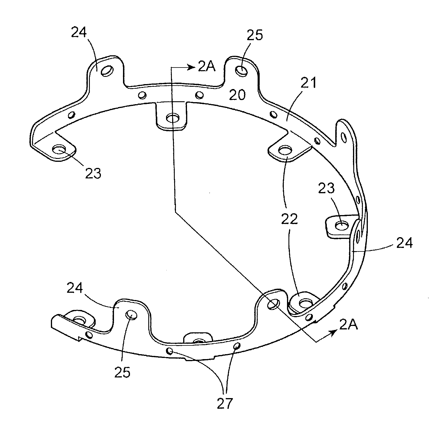
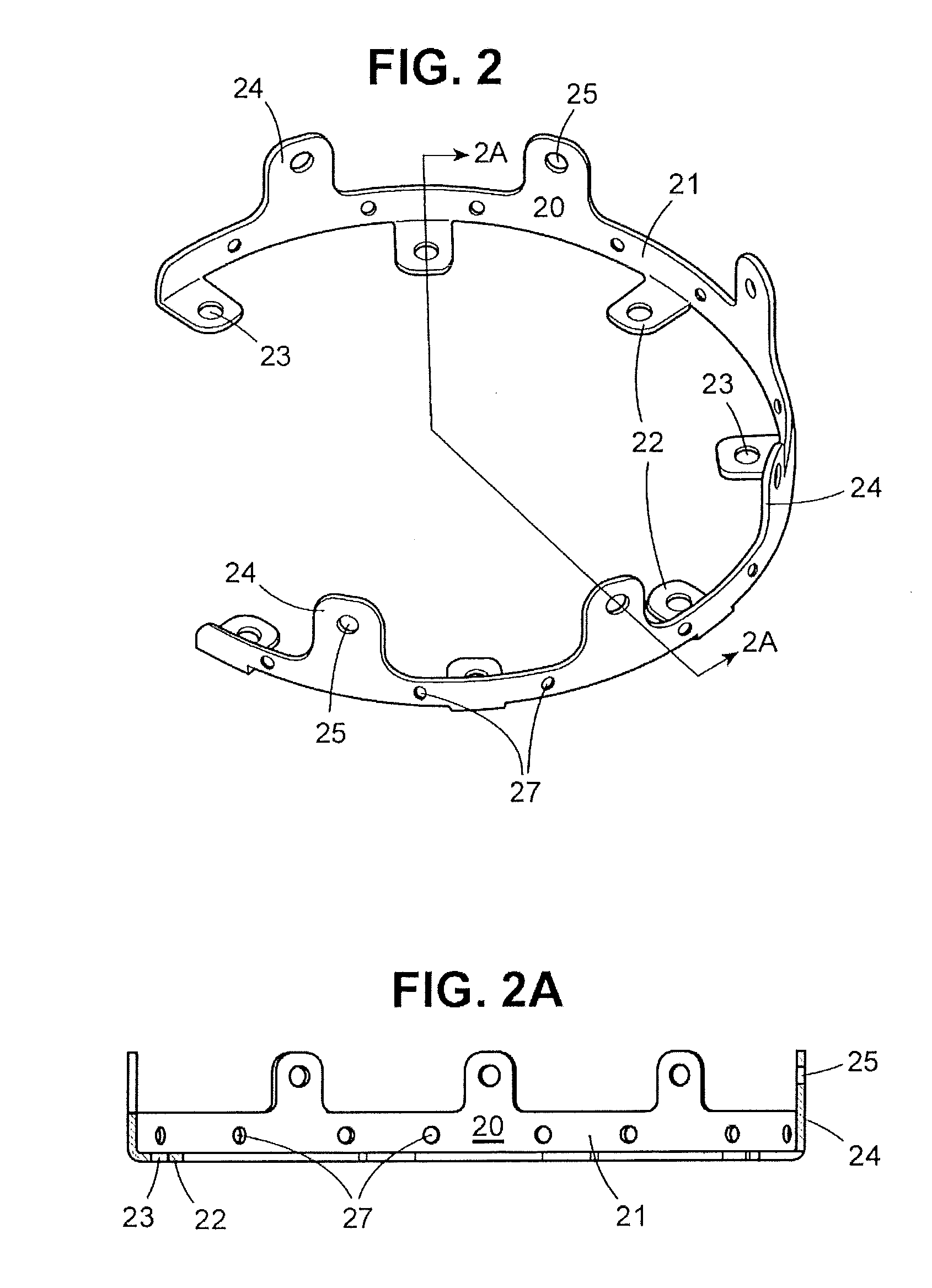
"The present invention provides surgical strip fasteners that are flexible and can be shaped to follow the perimeter contour of a skull flap and the opening in the skull from which the flap was removed. This allows the surgeon to reattach the flap in the same position, maintaining the contour of the skull. The strip fasteners can have tabs or flanges that are disposed over and adjacent to the skull flap and skull, and they can also have cavities or tubular elements that are disposed between the skull flap and skull. The side portions of the strip fasteners can have openings such as holes or slits to allow bone regrowth or secure the strip to the edge of either the skull flap or skull. The cavities or tubular elements can be filled or partially filled with medication, bone paste, bone growth enhancers, and the like. The cranial plugs can be used to plug small circular openings in the skull, and they can be filled or partially filled with the same substances as the strip fasteners."

Problems solved by technology

Because the fit is not exact due to the material removed by the craniotome, the flap can sag and sit slightly below the surface of the skull resulting in a depressed area that is obvious through the skin.
There is still the risk of a cosmetically objectionable depressed area resulting.
While this method results in a more stable and cosmetic result, it is relatively expensive, does not insure fusion and leaves foreign bodies at the surgical site.
This method can be faster than other methods and less expensive than the titanium plates, but more expensive than sutures or wires.
Just as with titanium plates and screws, fusion is not assured and foreign bodies remain in the patient.

Method used


Image

  • Craniotomy Closures and Plugs
  • Craniotomy Closures and Plugs
  • Craniotomy Closures and Plugs

Examples


Embodiment Construction

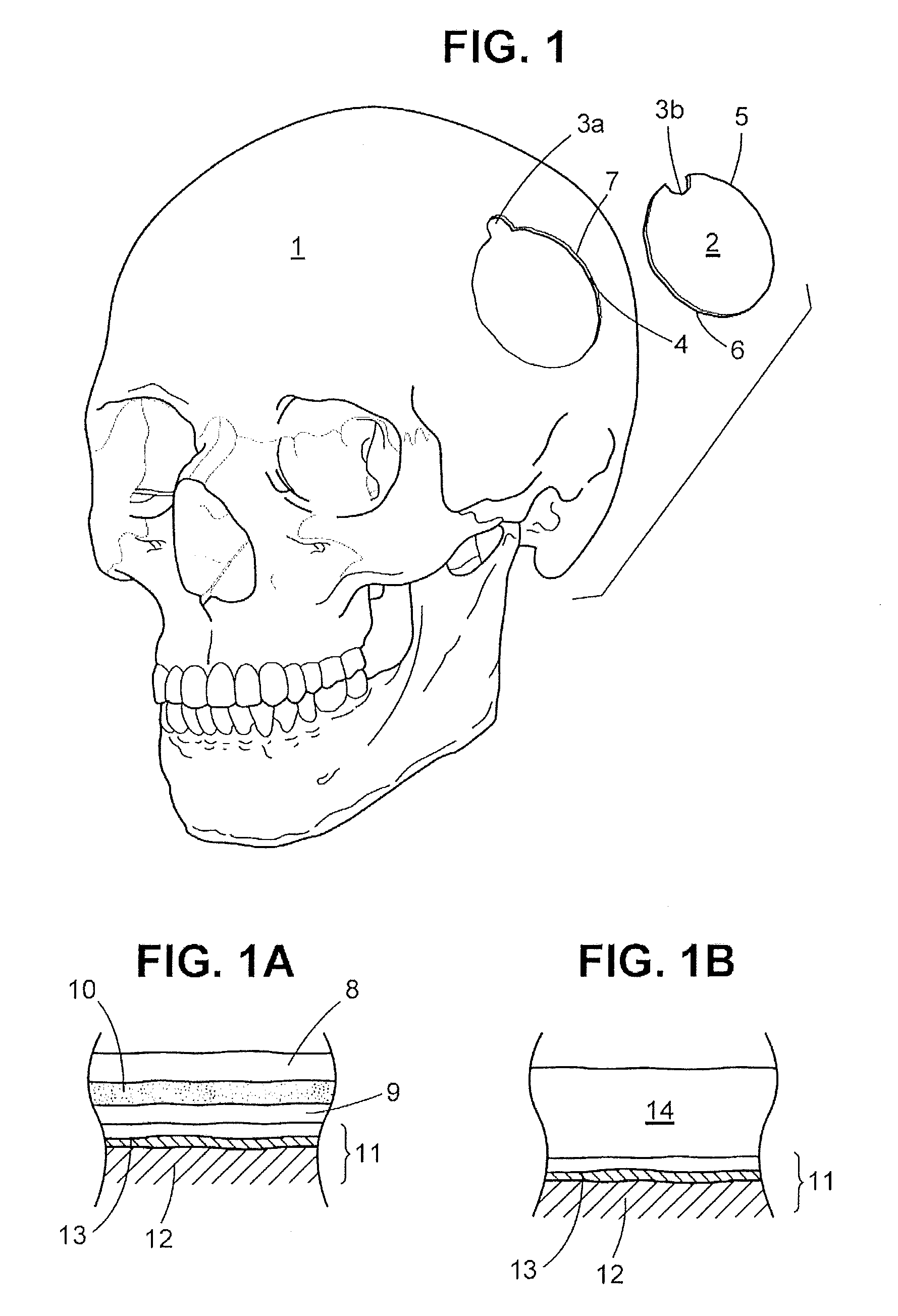
[0062]For reference, a human skull 1 with a craniotomy skull flap 2 is shown in FIG. 1. The skull flap 2 is defined by a burr hole 3 and the connecting osteotomy cut 4, wherein the skull portion of the burr hole is designated in FIG. 1 as 3a and the skull flap as 3b. The skull flap 2 has a perimeter contour 5 but it need not be of the particular shape shown and may have any number of burr holes 3. (See FIG. 15 for a 3 burr hole configuration.) On the opposing sides of the osteotomy cut 4 is the respective bone edge surface 6 of the skull flap 2 and the surrounding bone 7 of the skull 1, respectively. The bone edge surface 6 has a perimeter contour 5 generally matching the contour of the surrounding bone 7 of skull 1.

[0063]The skull 1 and skull flap 2 are either made from bone that has a three layer composition, as shown in FIG. 1A, or a single layer as shown in FIG. 1B. Referring to FIG. 1A, the outermost layer is the outer cortical bone 8 and the innermost layer is the inner cortic...


PUM


Abstract

Strip fasteners and cranial plugs for use in reattaching a skull flap removed during brain surgery and methods of using the same. The strip fasteners are flexible and can be shaped to follow the perimeter contour of the skull flap. The cranial plugs can be used to reattach the skull flap or they can be installed after the skull flap is reattached using the strip fasteners. In some embodiments, the cranial plug(s) and strip fasteners can be installed at the same time. The strip fasteners and cranial plugs are designed to encourage bone growth and healing of the skull flap and they can be used to deliver medication and bone growth enhancement compositions to the surgical site.

Description

CROSS REFERENCE TO RELATED APPLICATION[0001]This application is a Continuation of U.S. patent application Ser. No. 11 / 333,102 filed Jan. 17, 2006, of the same title, the entire disclosure of which is incorporated herein by reference.FIELD OF THE INVENTION[0002]The invention relates to surgical strip fasteners, particularly for use in reattaching a skull flap removed during brain surgery, and methods of reattaching the skull flap using the strip fasteners. The invention also has to do with cranial plugs used to fill small openings in the cranium or the burr holes made to facilitate cutting out a skull flap. In a further aspect, the invention relates to surgical strip fasteners and cranial plugs and methods which enhance bone growth and the consequent healing of the skull flap and the skull.BACKGROUND OF THE INVENTION[0003]Surgical access to the brain for neurosurgical procedures is created by removing a portion of the patient's skull, a procedure termed a craniotomy. The craniotomy i...

Claims


Application Information

Patent Timeline
Patent Type & Authority Applications(United States)
IPC IPC(8): A61B17/58
CPCY10T403/7176A61B17/688A61B17/68A61B17/58
Inventor RALPH, JAMES D.TROXELL, THOMAS N.
Owner FIRST COMMERCE BANK
Learn More