
Craniotomy Closures

a cranial valve and cranial tube technology, applied in the field of surgical fasteners, can solve the problem of limiting the flexibility of the projection, and achieve the effect of maintaining the skull contour

Active Publication Date: 2009-03-19
NEW AMSTERDAM LLC
View PDF74 Cites 93 Cited by
  • Summary
  • Abstract
  • Description
  • Claims
  • Application Information

AI Technical Summary

Benefits of technology

[0015]The surgical fasteners of the present invention allow the surgeon to reattach the skull flap in generally the same position from which it was removed, thereby maintaining the contour of the skull in a manner which is cosmetically desirable. The fasteners also position the flap in the skull in a manner which provides a generally even gap (the kerf) between the flap and the skull around the perimeter of the flap. Flexible surgical strips used in combination with the surgical fasteners can be shaped to follow the perimeter contour of the skull flap and, consequently, the contour of the opening in the skull from which the flap was removed. These strips are placed or implanted in the kerf between the flap and the skull. In a preferred embodiment, a craniotomy closure of the invention is comprised of at least two fasteners, used to reattach the skull flap, and one or more than one surgical strip.
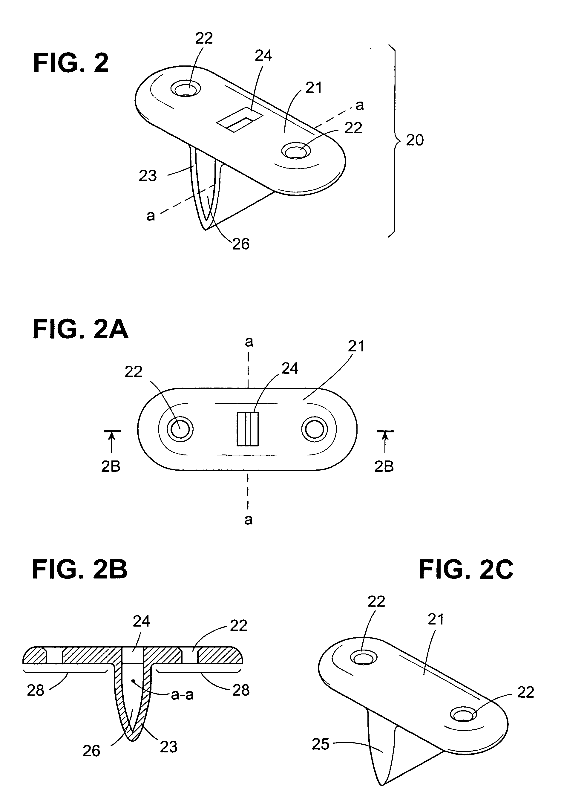
[0016]The fastener comprises a flange which is disposed over and adjacent to the skull flap and the skull. A projection extends from the underside of the flange. The projection extends into the kerf and acts as a spacer between the skull flap and the skull to make the generally even gap. In some embodiments, the projection can be flexible and somewhat wider than the kerf to make a snug fit. But the flexibility of the projection should be somewhat limited so that the function of the projection to act as a spacer is not compromised.
[0020]The surgical strips have side portions which are disposed between the skull flap and the skull when the strip is implanted. These side portions can optionally have openings such as holes, slits or lateral slots which permit bone regrowth. Additionally the slits may be oriented along a transverse axis through one sidewall and a portion of the bottom section of the strip, allowing the strip additional flexibility. The strips also can have a bottom portion. The tubular and solid shaped elements have bottom and top portions and these bottom and / or top portions also can have openings such as holes or lateral slots.

Problems solved by technology

But the flexibility of the projection should be somewhat limited so that the function of the projection to act as a spacer is not compromised.

Method used


Image

  • Craniotomy Closures
  • Craniotomy Closures
  • Craniotomy Closures

Examples


Embodiment Construction

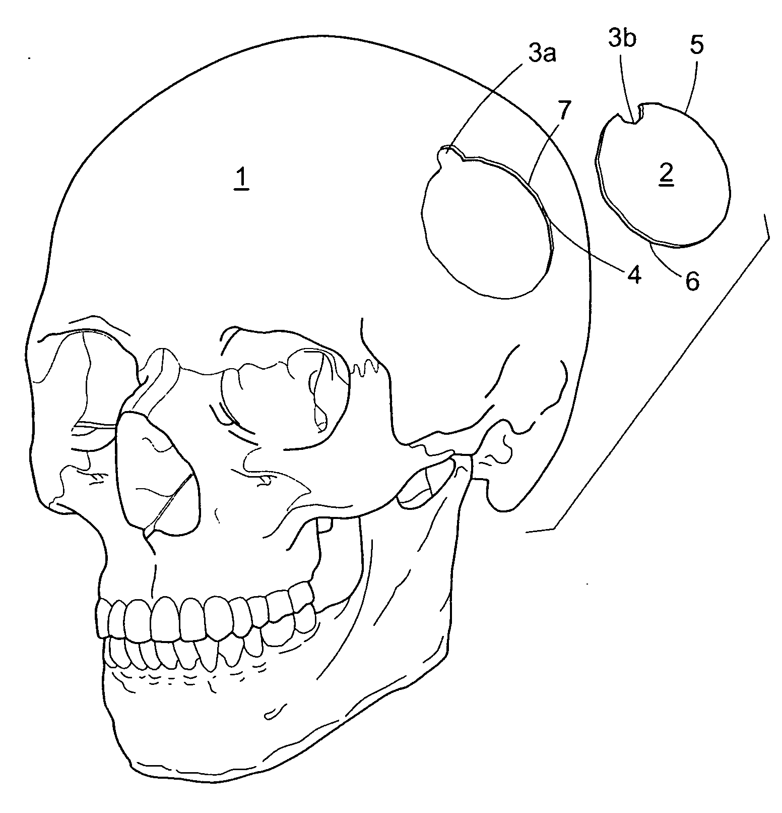
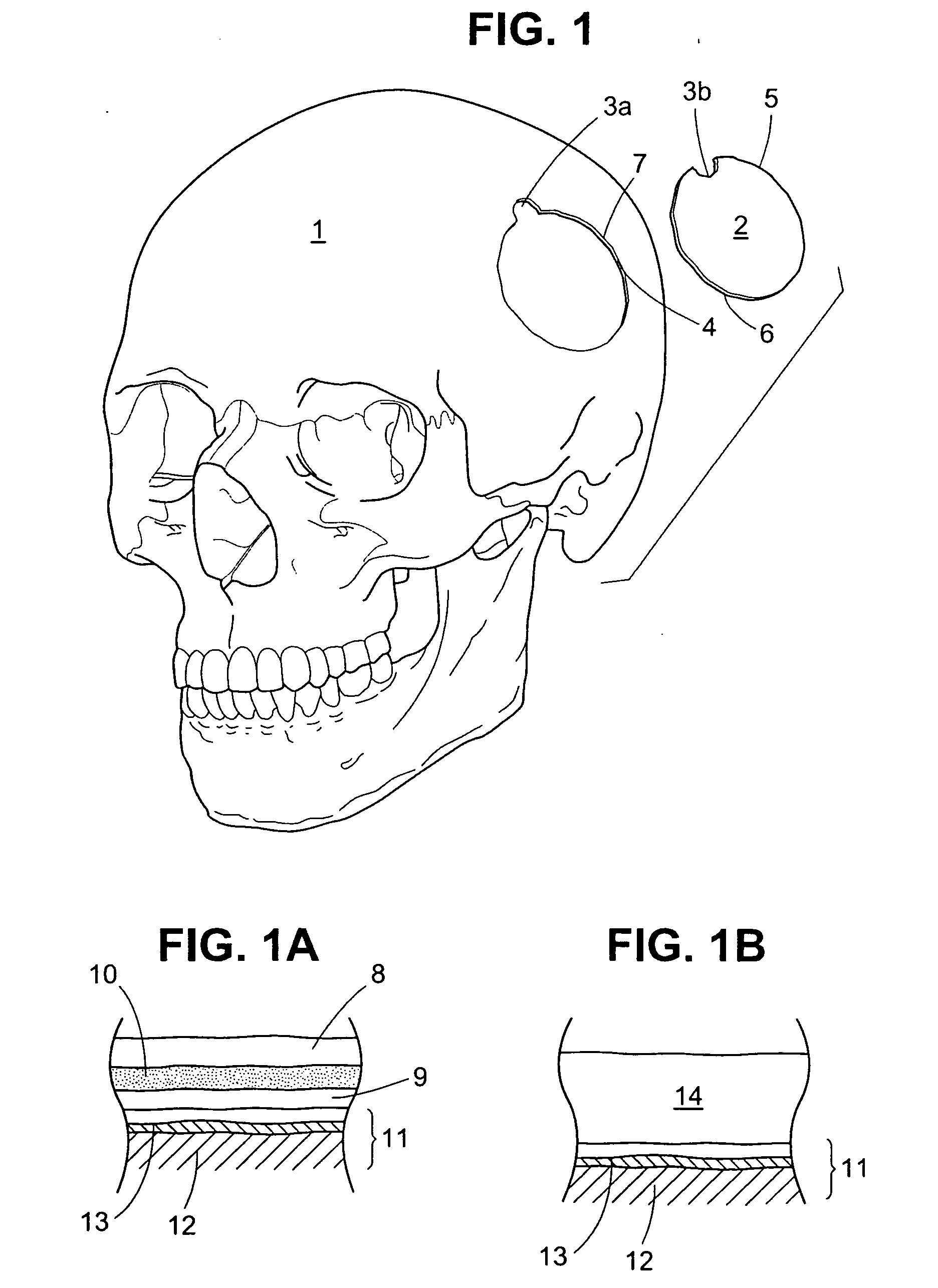
[0052]For reference, a human skull 1 with a craniotomy skull flap 2 (also referred to herein as a flap) is shown in FIG. 1. The skull flap 2 is defined by a burr hole 3 and the connecting osteotomy cut or kerf 4, wherein the skull portion of the burr hole is designated in FIG. 1 as 3a and the skull flap as 3b. The skull flap 2 has a perimeter contour 5 but it need not be of the particular shape shown and may have any number of burr holes 3. On the opposing sides of the osteotomy cut 4 is the respective bone edge surface 6 of the skull flap 2 and the surrounding bone 7 of the skull 1, respectively. The bone edge surface 6 has a perimeter contour 5 matching the contour of the surrounding bone 7 of skull 1.

[0053]The skull 1 and skull flap 2 are either made from bone that has a three layer composition, as shown in FIG. 1A, or a single layer as shown in FIG. 1B. Referring to FIG. 1A, the outermost layer is the outer cortical bone 8 and the innermost layer is the inner cortical bone 9. Be...


PUM


Abstract

Craniotomy closures comprising surgical fasteners are described for use in reattaching a skull flap removed from the skull of a patient during brain surgery. Methods of using the same are also described. Surgical strips used in combination with the fasteners are shaped to follow the perimeter contour of the skull flap. The craniotomy closures are designed to encourage bone growth and healing of the skull flap and they can be used to deliver medication and bone growth enhancement materials to the surgical site.

Description

CROSS-REFERENCE TO RELATED APPLICATION[0001]This application is a continuation-in-part of Ser. No. 11 / 333,102 filed Jan. 17, 2006.FIELD OF THE INVENTION[0002]The invention relates to surgical fasteners, particularly for use in reattaching a skull flap removed during brain surgery and methods of reattaching the skull flap using the fasteners. In further aspects, the invention relates to a surgical strip used in combination with the fasteners, methods of implanting the fasteners and strips of the invention and methods which enhance bone growth and the consequent healing of the skull flap and the skull.BACKGROUND OF THE INVENTION[0003]Surgical access to the brain for neurosurgical procedures is created by removing a portion of the patient's skull to provide an exposed area of soft tissue of the brain for surgery, a procedure termed a craniotomy. The craniotomy is determined by the location of the pathology within the brain, the safest / easiest access route and the degree of exposure req...

Claims


Application Information

Patent Timeline
Patent Type & Authority Applications(United States)
IPC IPC(8): A61F2/28
CPCA61B17/688A61B17/686
Inventor RALPH, JAMES D.TROXELL, THOMAS N.MICHELS, MARK
Owner NEW AMSTERDAM LLC
Learn More