
Method of manufacturing MEMS device

a manufacturing method and technology of a mems device, applied in the direction of impedence network, electrical apparatus, testing/measurement of semiconductor/solid-state devices, etc., can solve the problems of inability to adjust, limited range in which the operating frequency can be changed, and deviation in operation characteristics, so as to achieve accurate control of etching state, improve uniformity of surface etching for the movable portion, and improve the effect of operation characteristics

Inactive Publication Date: 2010-07-15
SEIKO EPSON CORP
View PDF5 Cites 14 Cited by
  • Summary
  • Abstract
  • Description
  • Claims
  • Application Information

AI Technical Summary

Benefits of technology

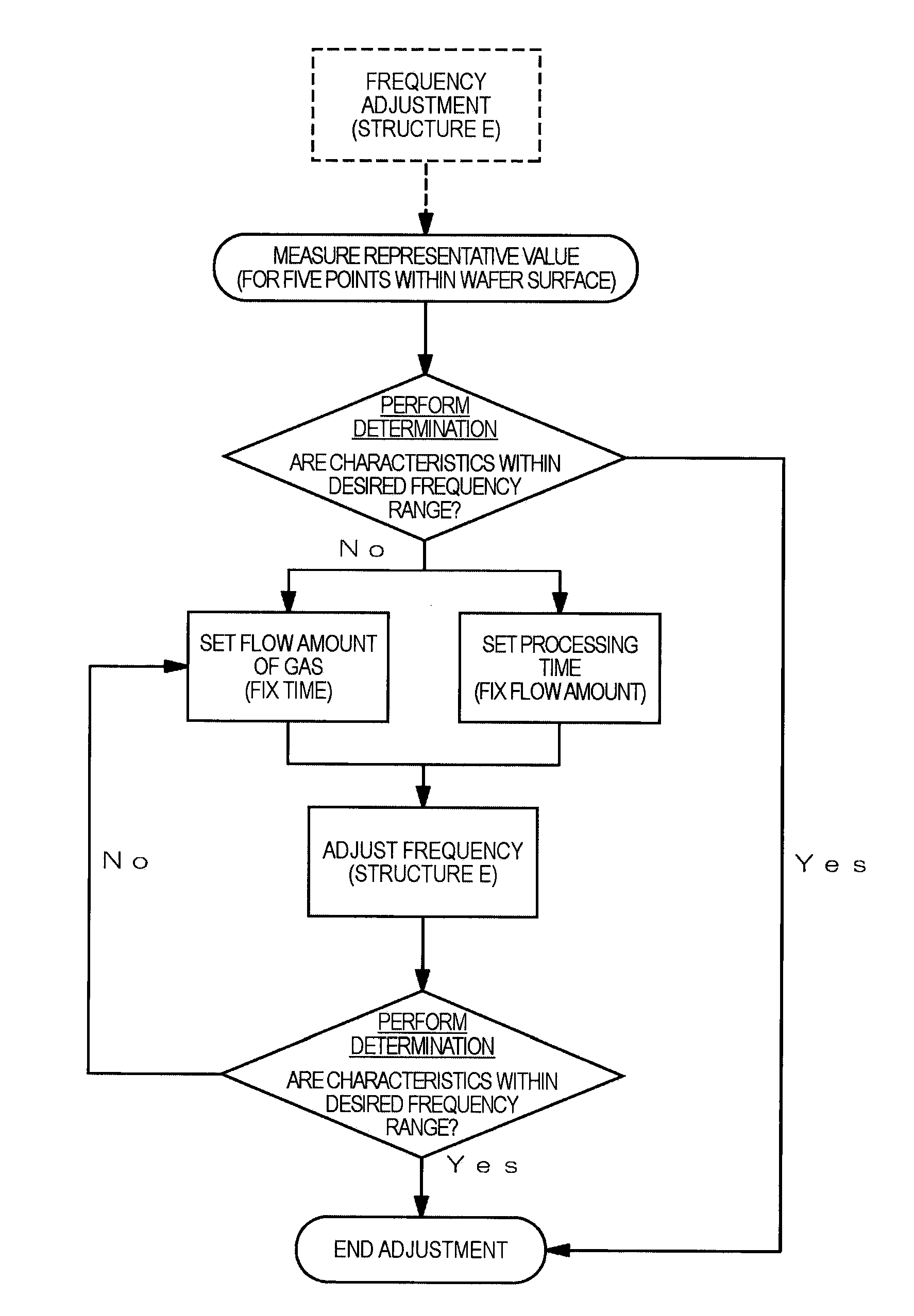
[0010]An advantage of some aspects of the invention is that it provides a method of adjusting an MEMS device capable of adjusting the structural size of the MEMS structure over a broad range and performing size adjustment uniformly without changing the operational aspects and a method of manufacturing the MEMS device using the method of adjusting the MEMS device.

Problems solved by technology

However, since the structure has a micro size, a deviation in the manufacturing process much affects the operating characteristics.
However, according to the above-described method of changing the operating frequency by changing the driving voltage, the range in which the operating frequency can be changed is limited.
Accordingly, there are cases where adjustment cannot be performed.
In addition, there is a problem that adjustable devices are limited to devices in which the operational aspects of a vibrator or the like depend on a driving voltage.
In addition, according to the above-described method using heating due to a current, since the method depends on the constituent material of a structure, there are cases where sufficient adjustment cannot be performed.
In addition, there is also a problem in that the operational aspects may be changed such as a change in the vibration mode due to a partial change of the movable portion or the like.
In addition, since gas-phase etching is used, even when surface etching is performed for the MEMS structure disposed inside the hollow portion of the covering structure, deviation in the uniformity of the etching does not easily occur.
In addition, since the MEMS structure is disposed inside the hollow portion of the covering structure, it is difficult to check directly the etched state by external visual recognition.
In particular, according to this aspect, since the MEMS structure is disposed inside the hollow portion of the covering structure, it is difficult to check directly the degree of the surface etching from the outside by visual recognition or the like.

Method used


Image

  • Method of manufacturing MEMS device
  • Method of manufacturing MEMS device
  • Method of manufacturing MEMS device

Examples


Embodiment Construction

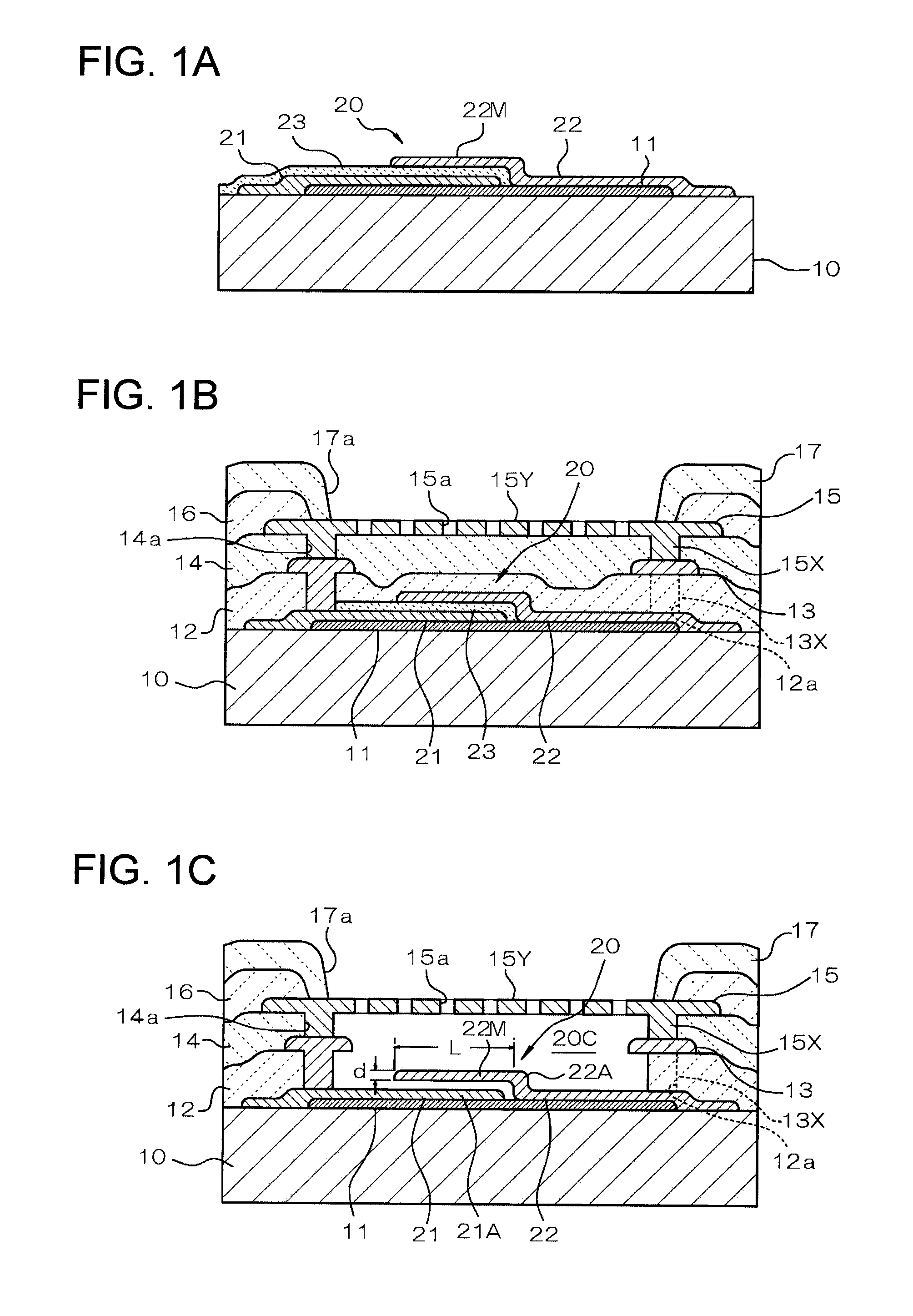
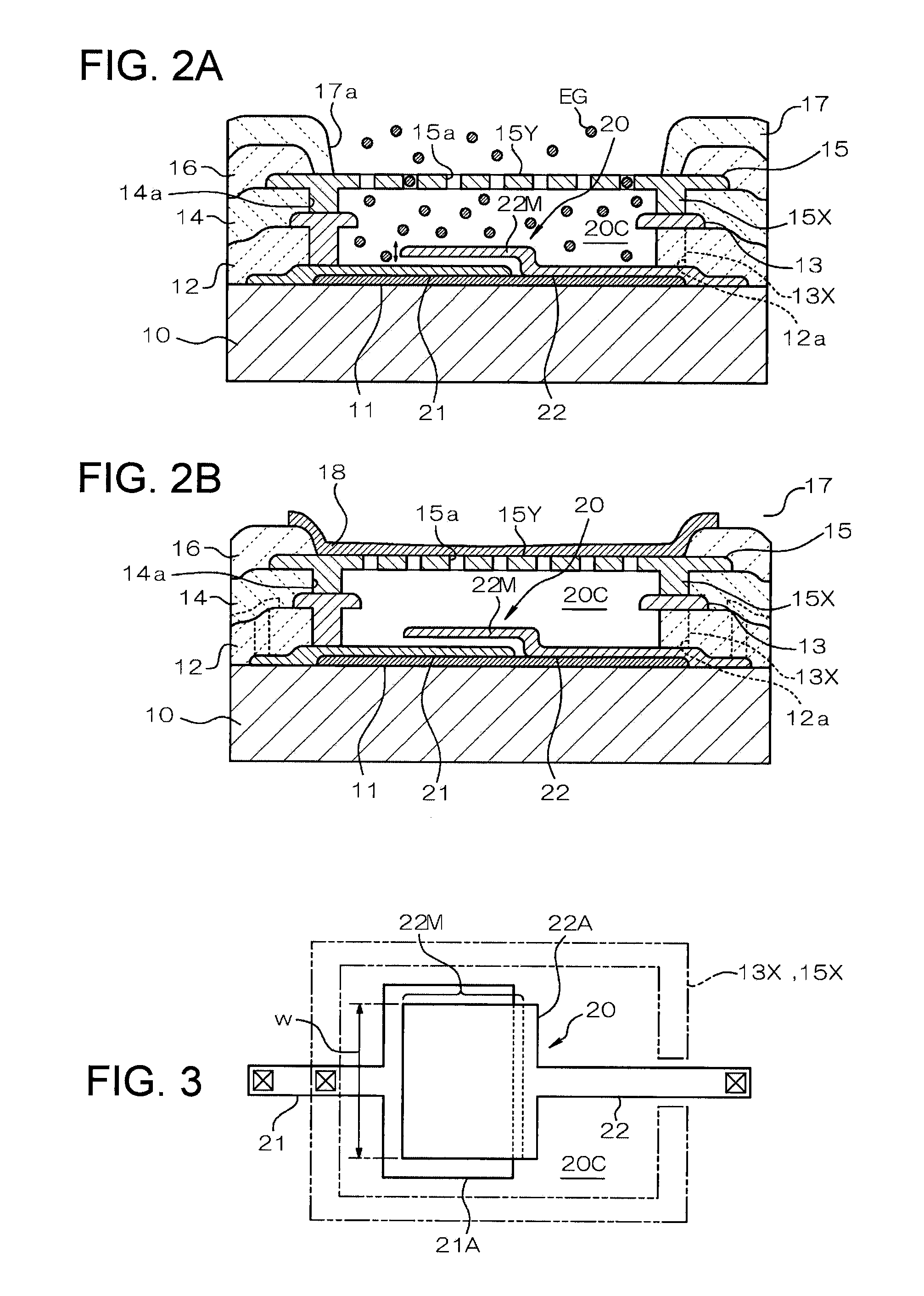
[0041]Next, exemplary embodiments of the invention will be described with reference to the accompanying drawings. First, a method of manufacturing an MEMS device according to an embodiment of the invention will be described with reference to FIGS. 1A to 1C and FIGS. 2A and 2B. FIGS. 1A to 1C and FIGS. 2A and 2B are schematic cross-sectional views showing each process of the method of manufacturing the MEMS device according to this embodiment.

[0042]As shown in FIG. 1A, in this embodiment, an MEMS device is manufactured which is configured by using a substrate (wafer) 10 formed of a semiconductor such as a single crystalline silicon as a base body and forming an MEMS structure 20 on the substrate 10. However, the substrate 10 is not limited to semiconductor and may be formed from various materials such as glass, ceramics, or resin.

[0043]On the surface of the substrate 10, an insulating film (not shown) made from silicon oxide or the like is formed as is necessary, and accordingly, ins...


PUM


Abstract

A method of manufacturing an MEMS device includes: forming a covering structure having an MEMS structure and a hollow portion, which is located on a periphery of the MEMS structure and is opened to an outside, on a substrate; and performing surface etching for the MEMS structure in a gas phase by supplying an etching gas to the periphery of the MEMS structure from the outside.

Description

BACKGROUND[0001]1. Technical Field[0002]The present invention relates to a method of manufacturing an MEMS device, and more particularly, to a manufacturing process for adjusting the structural size of an MEMS structure.[0003]2. Related Art[0004]MEMS (Micro Electro Mechanical Systems) relate to one of the technologies for forming micro structures. For example, MEMS relate to technology for producing a delicate electromechanical system of a micron order or such products. Generally, semiconductor chips have a circuit structure that is a two-dimensional pattern by manufacturing an electronic circuit by stacking thin films such as a silicon film, an oxidation film, and a metal film on a silicon substrate. However, when the technology for manufacturing the semiconductor chip, that is, semiconductor manufacturing technology is used in the MEMS, a leaf spring, a mirror, a rotation shaft, and the like of micron sizes are formed by forming a thin film on a substrate and by partially separati...

Claims


Application Information

Patent Timeline
Patent Type & Authority Applications(United States)
IPC IPC(8): H01L21/66
CPCH03H3/0077H03H2009/02511H03H2009/02496H03H9/2457
Inventor KIHARA, RYUJIINABA, SHOGO
Owner SEIKO EPSON CORP
Learn More