
Projection lens unit

a technology of projection lens and lens barrel, which is applied in the direction of mountings, instruments, optics, etc., to achieve the effect of increasing the size of the apparatus in which the lens barrel portion is accommodated and increasing the siz

Inactive Publication Date: 2010-07-15
FUJI PHOTO OPTICAL CO LTD
View PDF3 Cites 2 Cited by
  • Summary
  • Abstract
  • Description
  • Claims
  • Application Information

AI Technical Summary

Benefits of technology

[0008]The present invention has been accomplished to solve the above problems. The present invention proposes a structure of holding the projection lens without providing a flange portion, which is used for holding, in the lens barrel portion. That is, the present invention proposes a projection lens unit in which the lens barrel can be held without increasing the size in the thickness direction of the small projector.

Problems solved by technology

Because of the increased size, a commodity value of the portable small projector, which is made on the assumption that the projector is carried, is lowered, which is a big problem.

Method used


Image

  • Projection lens unit
  • Projection lens unit
  • Projection lens unit

Examples


Embodiment Construction

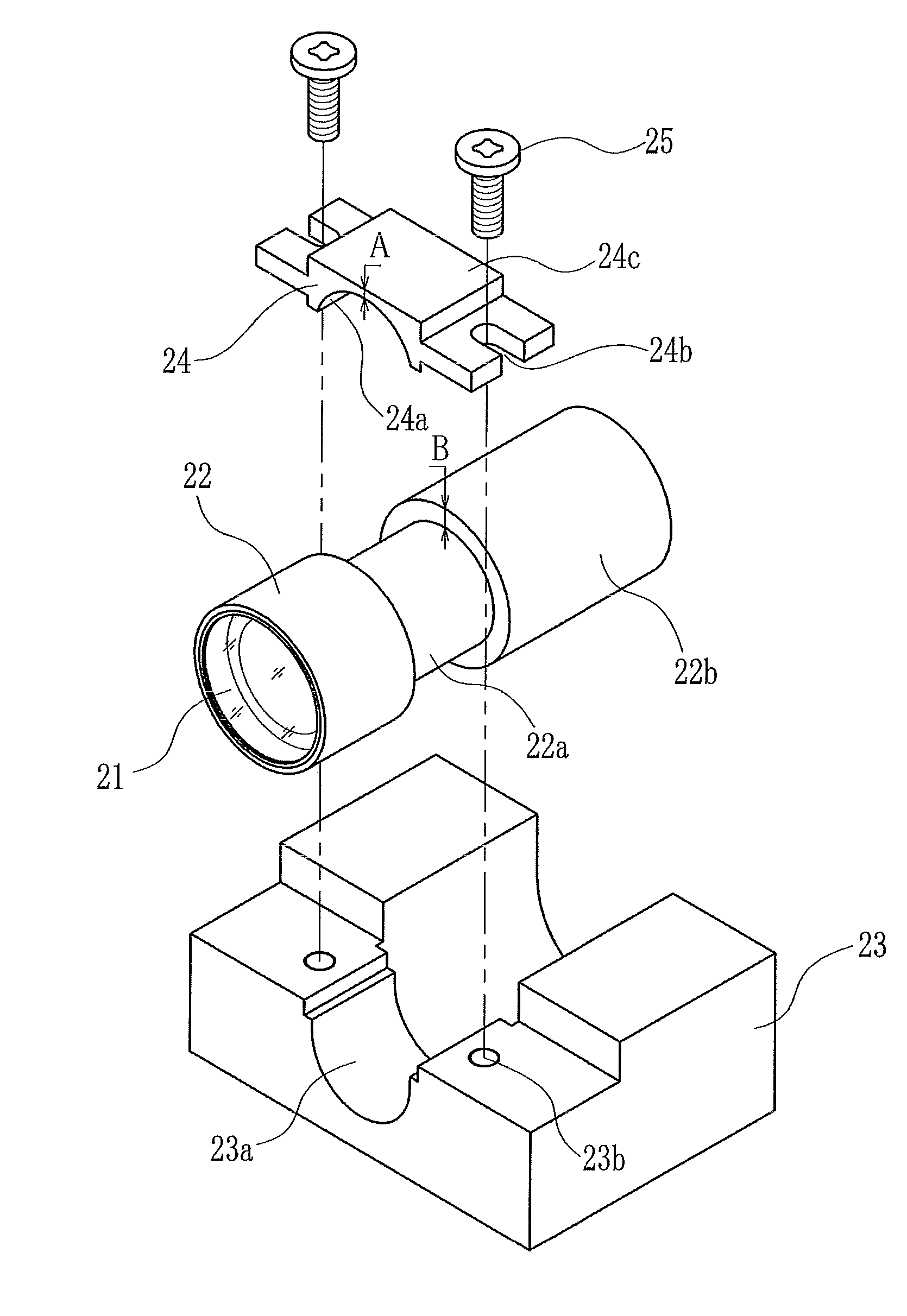
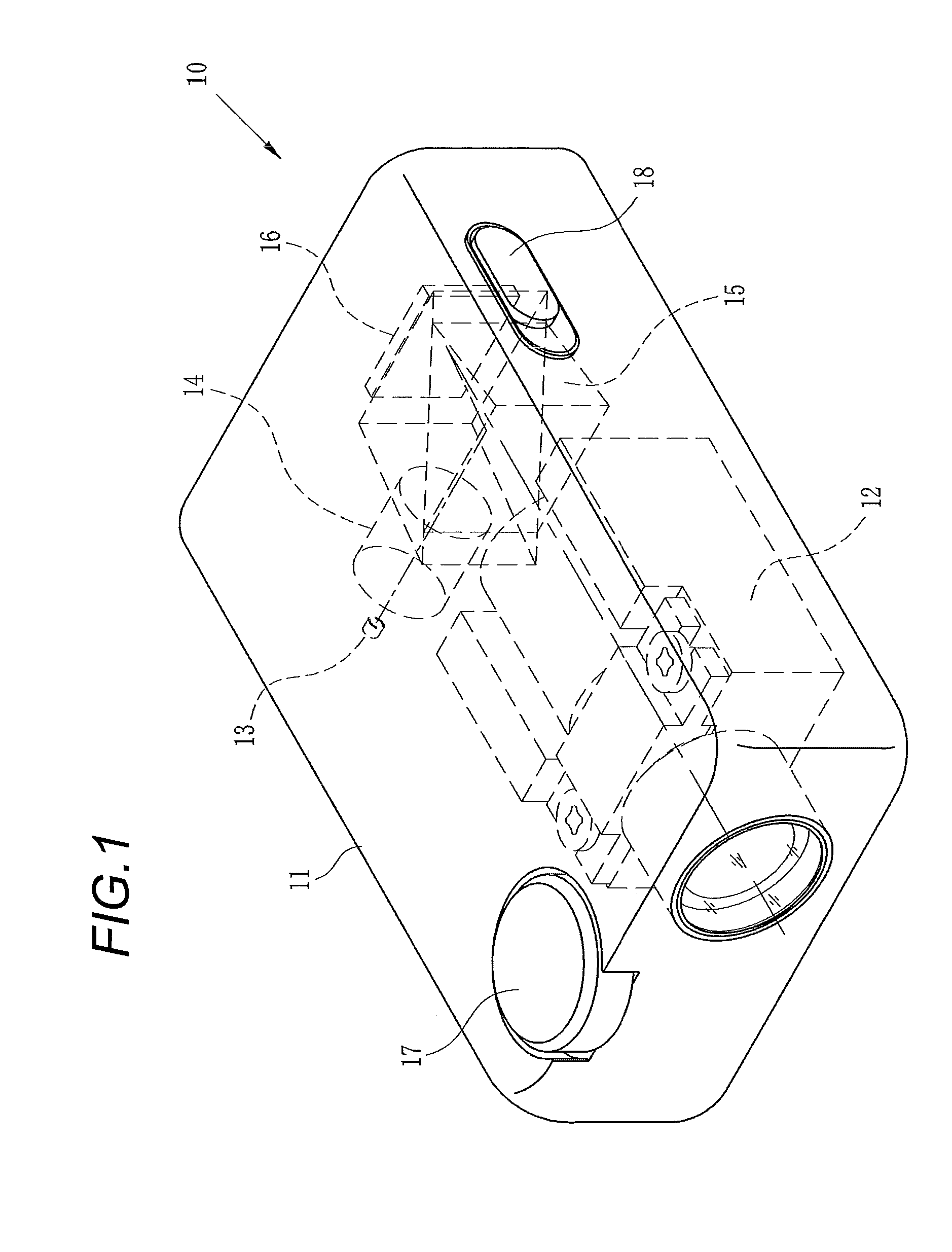
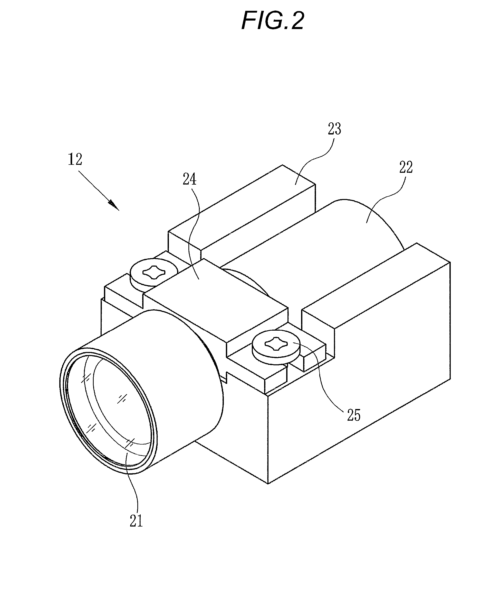
[0018]As shown in FIG. 1, the portable type small projector 10 is composed as follows. The housing 11, which is formed to be a substantial rectangular parallelepiped, accommodates a projection lens unit 12 of the present invention, an LED 13 which is used as a light source, an illumination optical system 14, a total internal reflection prism 15, and a reflection type LCD 16 which will be referred to as an LCD hereinafter. The focus adjusting dial 17, which adjusts the focus of an image projected on a screen by moving a portion of the lens composing the optical system of the projection lens unit 12, and the power switch 18 are provided so that the operating portions can be exposed from the housing 11. Light emitted from the LED 13 transmits the illumination optical system 14, which includes a filter and an integrator, and is incident on the total internal reflection prism 15, so that the light is formed to be image light containing an image displayed by the LCD 16. The thus formed im...


PUM


Abstract

A projection lens unit includes: a projection lens having a first optical system for focusing incident image light and also having a second optical system for magnifying and projecting the image light focused by the first optical system; a lens barrel member for accommodating the projection lens and having a small diameter portion in which a joining portion of the first and the second optical system is formed to be the thinnest; a holding member having a first holding face on which the small diameter portion is mounted; and a presser member having a second holding face which holds the small diameter portion together with the first holding face. The holding member is fixed to a housing on which the projection lens unit is mounted. The presser member does not protrude upward from the lens barrel member arranged in a dead space of the small diameter portion.

Description

[0001]The present application claims priority from Japanese Patent Application No. 2009-0005567 filed on Jan. 14, 2009, the entire content of which is incorporated herein by reference.BACKGROUND OF INVENTION[0002]1. Field of the Invention[0003]The present invention relates to a projection lens unit mounted on a portable type ultra-small projector and projecting an image, which is formed by an image forming apparatus, on a screen.[0004]2. Description of the Related Art[0005]Recently, portable type electronic apparatus have come into wide use in which a light projector is incorporated into a personal computer, a mobile phone or a digital camera so that a projecting function can be added in addition to the original function of the electronic apparatus. Further, portable type ultra-small projectors, on which only the projecting function is mounted, have been on the market. There is a strong demand of reducing the sizes of the light projectors incorporated into those portable type electr...

Claims


Application Information

Patent Timeline
Patent Type & Authority Applications(United States)
IPC IPC(8): G02B7/02
CPCG02B13/16G02B7/021
Inventor KURODA, YASUTO
Owner FUJI PHOTO OPTICAL CO LTD
Learn More