Single element sensor with multiple outputs

a single element sensor and output technology, applied in the field of sensors, can solve the problems of inability to accurately compensate in real time for the effect of temperature changes on the response of optical sensors, cross-sensitivity of temperature sensors, and inability to accurately compensate in real time for the effect of temperature changes on the optical sensor, etc., to facilitate real-time monitoring, facilitate the effect of cross-sensitivity exploitation

Inactive Publication Date: 2010-07-08
DUBLIN CITY UNIVERSITY
View PDF9 Cites 10 Cited by
  • Summary
  • Abstract
  • Description
  • Claims
  • Application Information

AI Technical Summary

Benefits of technology

[0012]The sensor element is desirably luminescent based. Such a sensor element may include one or more luminophores, the term being used in its generic form and intending to include both fluorphores and phosphors. Using such luminophores, the present invention provides a sensor that may operably implement a technique that facilitates the exploitation of sensor cross-sensitivity in order to extract multianalyte information from a single sensor element that employs only one luminophore. In accordance with the teaching of the invention a technique is provided that facilitates the real-time, simultaneous monitoring of for example temperature and the analyte concentration of interest without the need for an independent temperature sensor or an additional, temperature-sensitive luminophore.

Problems solved by technology

Unfortunately it is known that a sensor that is provided for sensing a particular analyte may have response characteristics dependent on parameters other than the concentration of the analyte desiring sensing.
Unfortunately, a key problem for such sensors is their cross-sensitivity to temperature.
This impairs the accuracy of the sensor, which is typically based on a luminescent complex that has been encapsulated in a solid matrix, due to the fact that the independent temperature sensor does not measure the temperature of the sensor matrix but instead measures that of the surrounding environment.
Such independent sensors invariably possess a different response time to temperature than that of the sensor matrix, with the result that it is not possible to accurately compensate in real time for the effect of temperature changes on the optical sensor response.
If a single source is to be used, a great deal of effort must be applied to the synthesis of spectrally compatible luminophores.
Furthermore, those techniques were limited specifically to the detection of two analytes using Dual Luminophore Referencing (DLR).

Method used


Image

  • Single element sensor with multiple outputs
  • Single element sensor with multiple outputs
  • Single element sensor with multiple outputs

Examples


Embodiment Construction

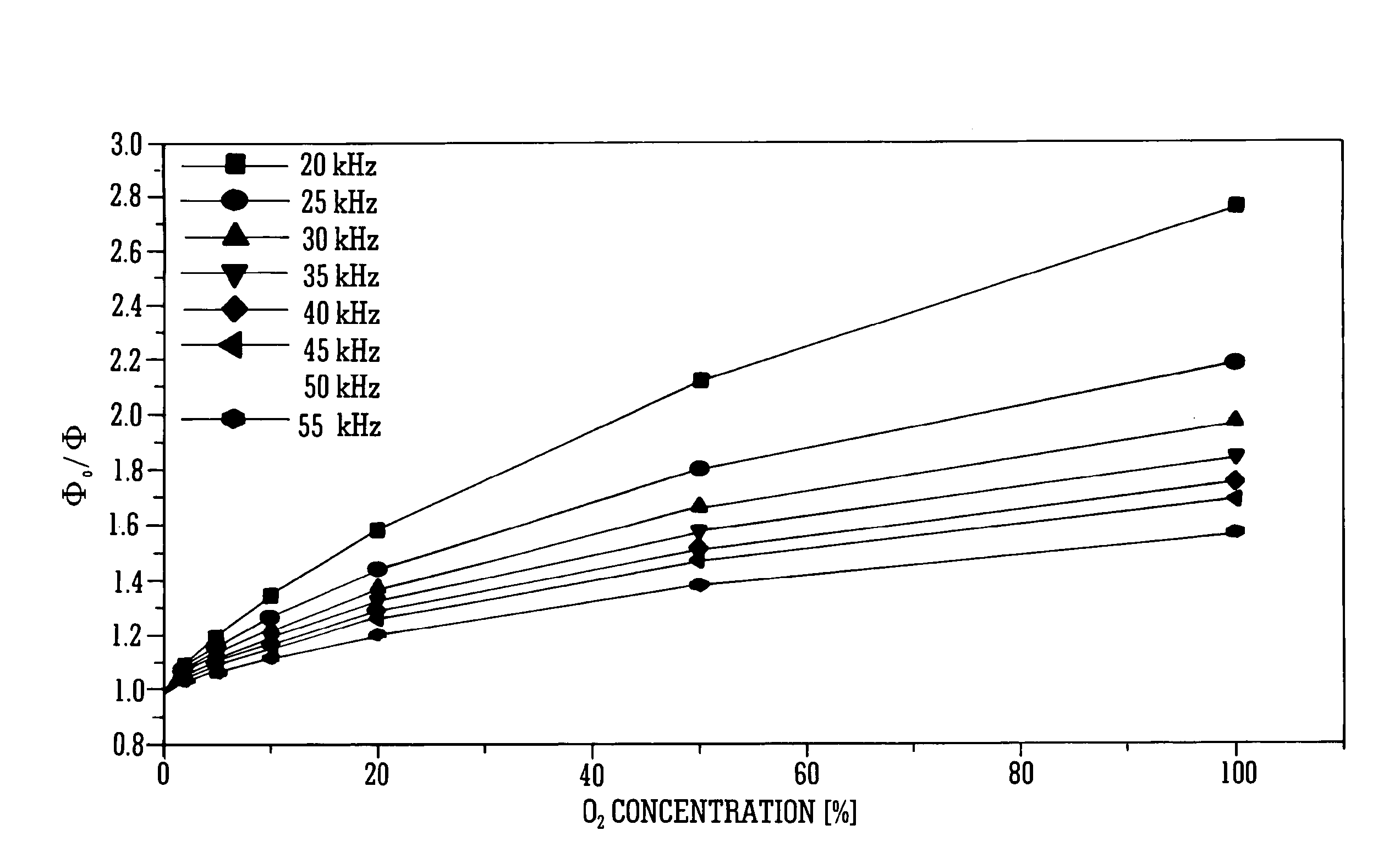
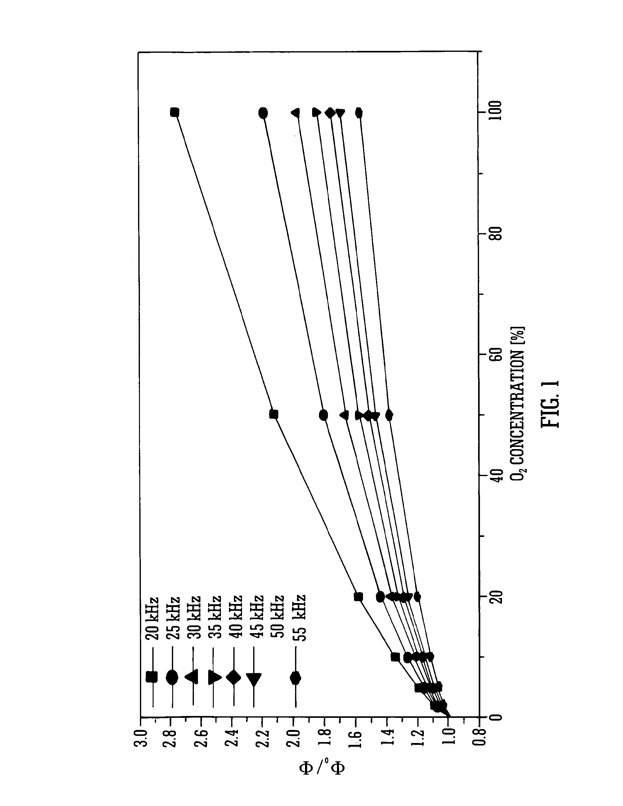
[0019]A sensor provided in accordance with the teaching of the present invention includes a sensor element having multi-phase response to excitation that can be analysed to provide information on the presence of one or more analytes. Within this context excitation of the sensor may provide two or more phase responses from the sensor element. In accordance with the teaching of the invention, a sensed analyte will have different response characteristics in different phase response outputs from the sensor element and this can be used to characterize the analyte or indeed to discriminate between two or more analytes.

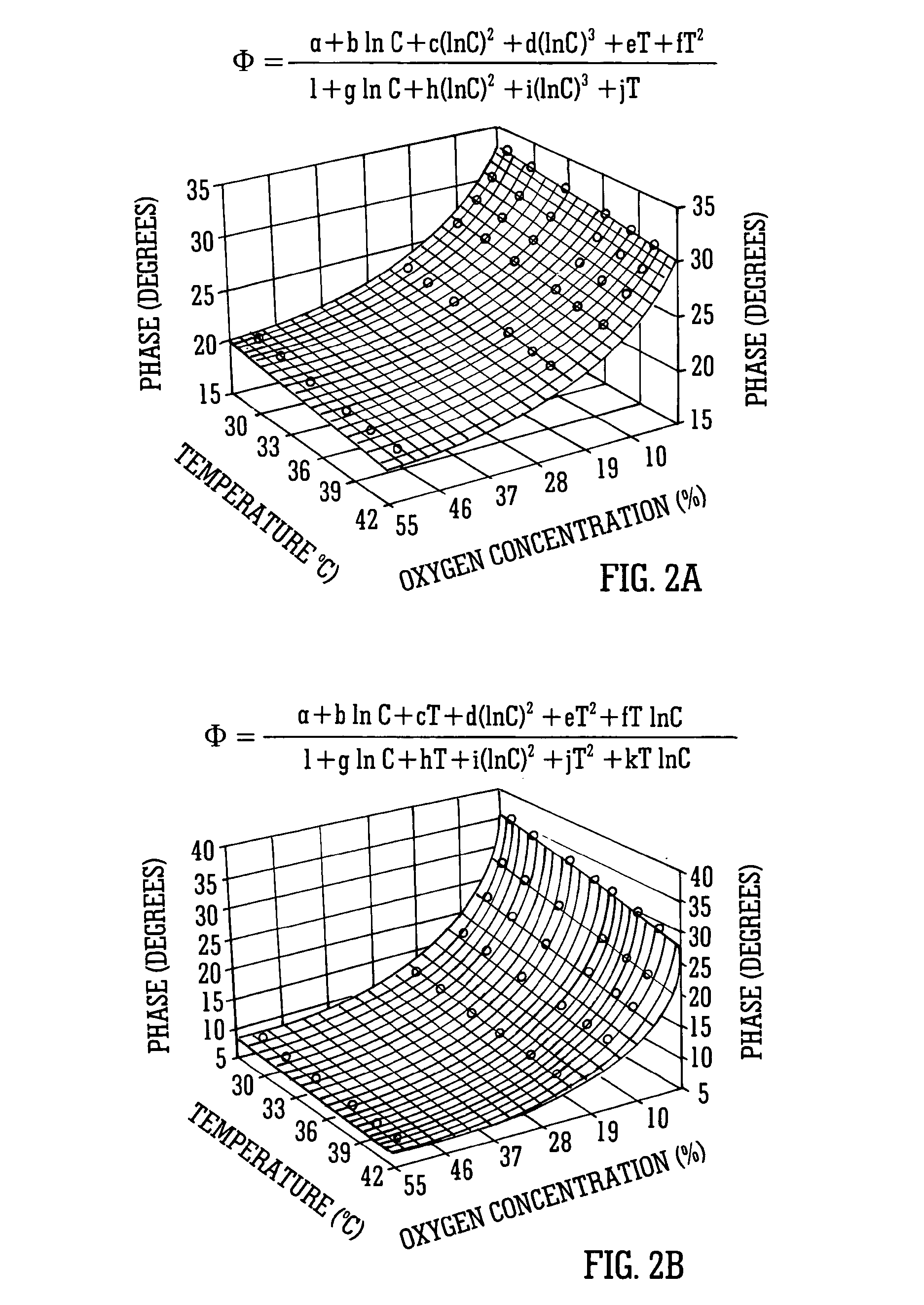
[0020]To assist with an understanding of this teaching of the invention an exemplary arrangement providing an optical oxygen sensor with intrinsic temperature compensation will now be described. Such a sensor implements a technique that requires only a single, unmodified sensor element and a single excitation source and thus can be extended to the simultaneous detection of m...


PUM

PropertyMeasurementUnit
multi-frequencyaaaaaaaaaa
phase responseaaaaaaaaaa
temperatureaaaaaaaaaa

Abstract

An analyte sensor is described. The sensor employs a single sensor element which provides a plurality of phase outputs in response to excitation by a modulated excitation source. The plurality of phase outputs may be analysed to provide information on the presence of one or more analytes.

Description

BACKGROUND[0001]1. Technical Field[0002]The present disclosure generally relates to the field of sensors and particularly to sensors having a sensor element which is responsive to excitation by an excitation source to generate a plurality of phase response outputs, analysis of the outputs providing information on one or more analytes. In a preferred arrangement the invention relates to luminescence-based optical sensors, and more particularly, to sensors based on a technique that exploits the cross-sensitivity of luminescence sensors that are based on phase detection methods in order to extract quantitative information on multiple analytes from the response of a single sensing element.[0003]2. Description of the Related Art[0004]Sensors are well known and used for detecting any number of different analytes. Unfortunately it is known that a sensor that is provided for sensing a particular analyte may have response characteristics dependent on parameters other than the concentration o...

Claims


Application Information

Patent Timeline
Patent Type & Authority Applications(United States)
IPC IPC(8): G01N21/64
CPCA61B5/0873G01N21/6408G01N21/643G01N21/783G01N21/80G01N21/81G01N2201/1296G01N33/004G01N33/0054G01N2021/6432G01N2021/6441G01N2201/0625G01N33/0037Y02A50/20
Inventor BURKE, CONORMOORE, JOHN
Owner DUBLIN CITY UNIVERSITY
Why Eureka
Try Eureka