
Method and apparatus for fuel injection in a turbine engine

a technology of turbine engines and fuel injection, which is applied in the direction of machines/engines, mechanical equipment, lighting and heating apparatus, etc., can solve the problems of inability of hbtu fuel nozzles to mix lbtu fuel with compressed air in a suitable ratio or mixing, and the nozzles may not be suitabl

Inactive Publication Date: 2010-07-08
GENERAL ELECTRIC CO
View PDF16 Cites 112 Cited by
  • Summary
  • Abstract
  • Description
  • Claims
  • Application Information

AI Technical Summary

Benefits of technology

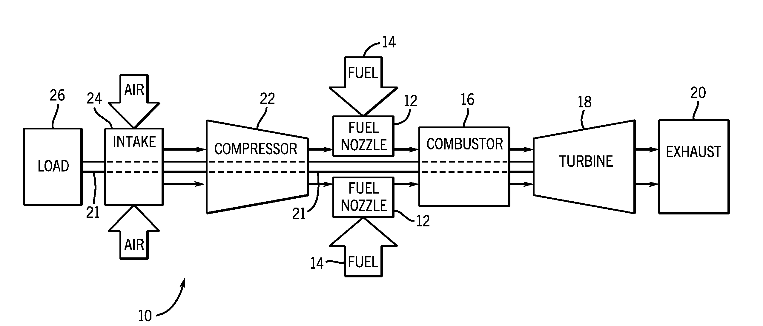
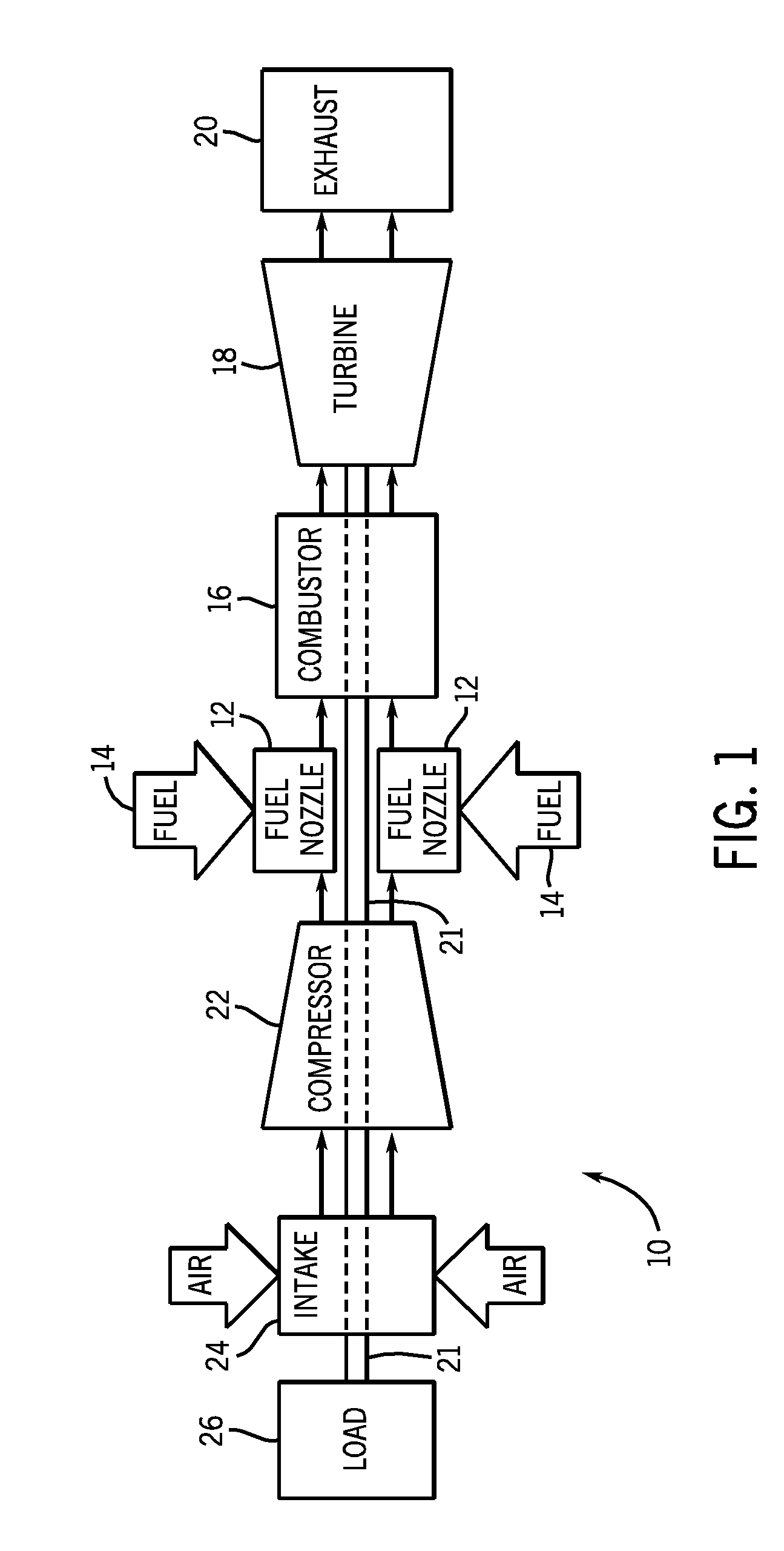
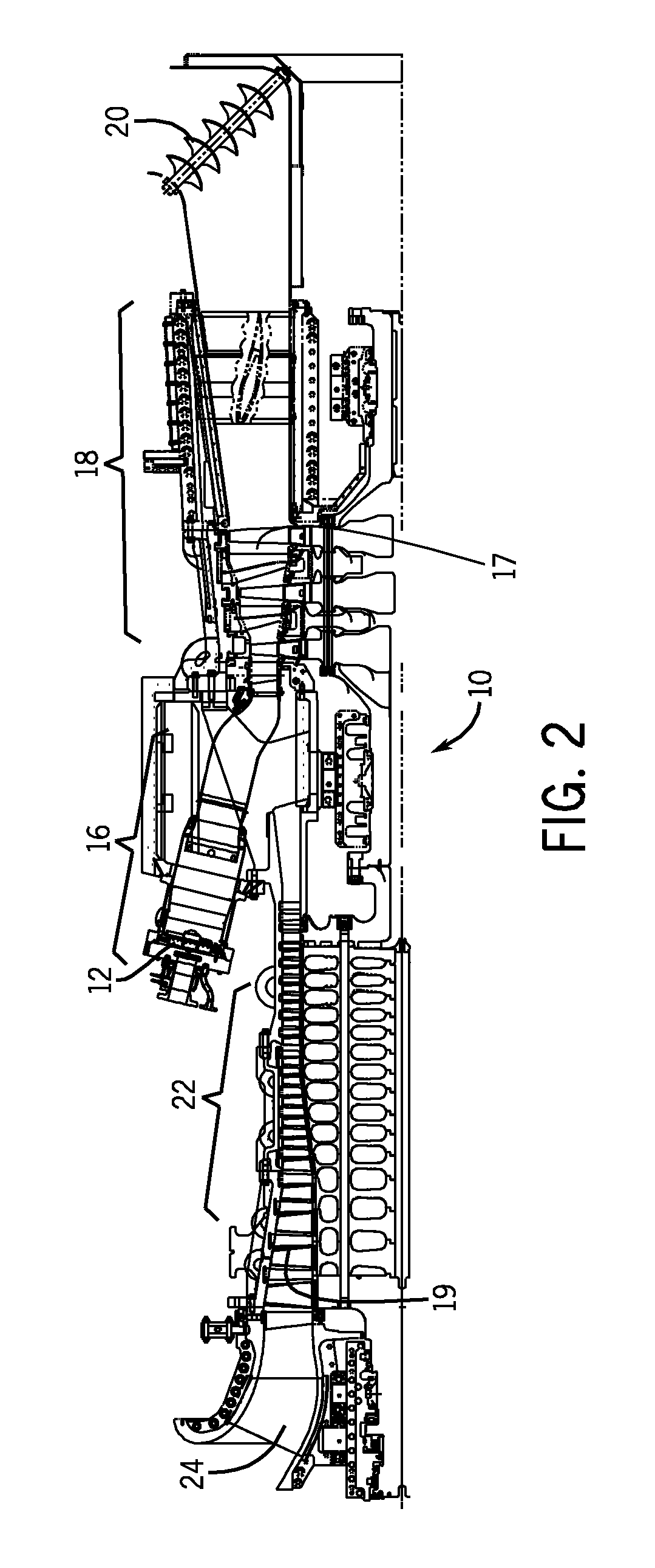
[0036]Technical effects of the invention include an improved flexibility of fuel usage in turbine systems, by enabling a lean mixture of LBTU fuel and air. The improved mixing arrangement provides for the air-fuel mixture to occur downstream of a fuel nozzle. An embodiment enables a reduced incidence of early flameholding, flashback, and / or auto ignition within the combustor and fuel nozzle components. The downstream air-fuel mixture enables combustion in a downstream location within the combustor, thereby providing an optimized and efficient turbine combustion process. This may result in increased performance and reduced emissions.

Problems solved by technology

Unfortunately, the nozzles may not be suitable for mixing compressed air with a low BTU (LBTU) fuel.
As a result, the HBTU fuel nozzles may not be capable of mixing the LBTU fuel with compressed air in a suitable ratio or mixing intensity.

Method used


Image

  • Method and apparatus for fuel injection in a turbine engine
  • Method and apparatus for fuel injection in a turbine engine
  • Method and apparatus for fuel injection in a turbine engine

Examples


Embodiment Construction

[0012]This written description uses examples to disclose the invention, including the best mode, and also to enable any person skilled in the art to practice the invention, including making and using any devices or systems and performing any incorporated methods. The patentable scope of the invention is defined by the claims, and may include other examples that occur to those skilled in the art. Such other examples are intended to be within the scope of the claims if they have structural elements that do not differ from the literal language of the claims, or if they include equivalent structural elements with insubstantial differences from the literal languages of the claims.

[0013]When introducing elements of various embodiments of the present invention, the articles “a,”“an,”“the,” and “said” are intended to mean that there are one or more of the elements. The terms “comprising,”“including,” and “having” are intended to be inclusive and mean that there may be additional elements ot...


PUM


Abstract

In one embodiment, a turbine system, may include a fuel nozzle, that includes a plurality of fuel passages and a plurality of air passages offset in a downstream direction from the fuel passages. In the embodiment, an air flow from the air passages is configured to intersect with a fuel flow from the fuel passages at an angle to induce swirl and mixing of the air flow and the fuel flow downstream of the fuel nozzle.

Description

BACKGROUND OF THE INVENTION[0001]The present disclosure relates generally to a gas turbine engine and, more specifically, to a fuel nozzle with improved fuel-air mixing characteristics.[0002]Fuel-air mixing affects engine performance and emissions in a variety of engines, such as gas turbine engines. For example, a gas turbine engine may employ one or more nozzles to facilitate fuel-air mixing in a combustor. Typically, the nozzles are configured to facilitate mixing of compressed air with a high British thermal unit (i.e., high BTU or HBTU) fuel. Unfortunately, the nozzles may not be suitable for mixing compressed air with a low BTU (LBTU) fuel. For example, the LBTU fuel may produce a low amount of heat per volume of fuel, whereas the HBTU fuel may produce a high amount of heat per volume of fuel. As a result, the HBTU fuel nozzles may not be capable of mixing the LBTU fuel with compressed air in a suitable ratio or mixing intensity.BRIEF DESCRIPTION OF THE INVENTION[0003]In one e...

Claims


Application Information

Patent Timeline
IPC IPC(8): F02C7/22
CPCF23D2900/14701F23R3/12F23R3/286F23R3/34F23R3/36F23R2900/00002Y02T50/675Y02T50/678Y02T50/60
Inventor BERRY, JONATHAN DWIGHTBROWN, JAMES T.KARIM, HASANSIMONS, GIRARD A.
Owner GENERAL ELECTRIC CO
Learn More