
Single-stage isolated high power factor ac/dc converter with leakage inductor energy recovery function

Active Publication Date: 2010-07-01
MACROBLOCK INC
View PDF15 Cites 20 Cited by
  • Summary
  • Abstract
  • Description
  • Claims
  • Application Information

AI Technical Summary

Benefits of technology

[0012]In order to improve the current AC / DC converters, such that the AC / DC converters have a high power factor, a high circuit efficiency, fewer circuit elements, and a lower cost, the present invention is directed to a single-stage isolated high power factor AC / DC converter that integrates a buck-boost circuit with a flyback converter or a forward converter, and is further directed to a driving circuit using such a circuit to drive a load (for example, an LED), so as to achieve power factor correction (PFC), improve an efficiency, and reduce a circuit cost. A single-stage converter circuit according to an embodiment of the present invention can return energy stored in a leakage inductor of a transformer in the circuit to an input capacitor, thus improving the conversion efficiency.
[0014]In the present invention, the energy stored in the leakage inductor of the transformer in a flyback converter or a forward converter is returned to the input capacitor through the energy recovery path. Thus, the problem caused by the leakage inductor of the transformer in the flyback converter or the forward converter can be solved without using any additional element, thus improving the circuit efficiency.
[0015]The AC / DC converter circuit according to the embodiment of the present invention not only has the advantage of electrical isolation, but also can meet the requirements in the industry for high power factor, high efficiency, and low cost (by reducing circuit elements).
[0016]The AC / DC converter circuit according to the embodiment of the present invention not only meet PFC requirements of safety specifications, but also can achieve functions of electrical isolation (conforming to the safety specifications), multi-winding output, and voltage level adjustment through the transformer, and is applicable to various AC voltages, thus avoiding unstable output when the mains voltage is unstable or suddenly drops. In addition, as the PFC circuit is integrated with the power conversion circuit into the single-stage converter circuit, the circuit structure is simplified and the number of elements used in the circuit is reduced, thus reducing the cost.
[0017]According to the embodiment of the present invention, as the PFC circuit is integrated with the power conversion circuit into the single-stage converter circuit, one power conversion stage is omitted, thus improving the conversion efficiency. As compared with a two-stage architecture, the circuit in the single-stage architecture is easy to control, uses two-stage LC filtering, and outputs a very low ripple voltage.

Problems solved by technology

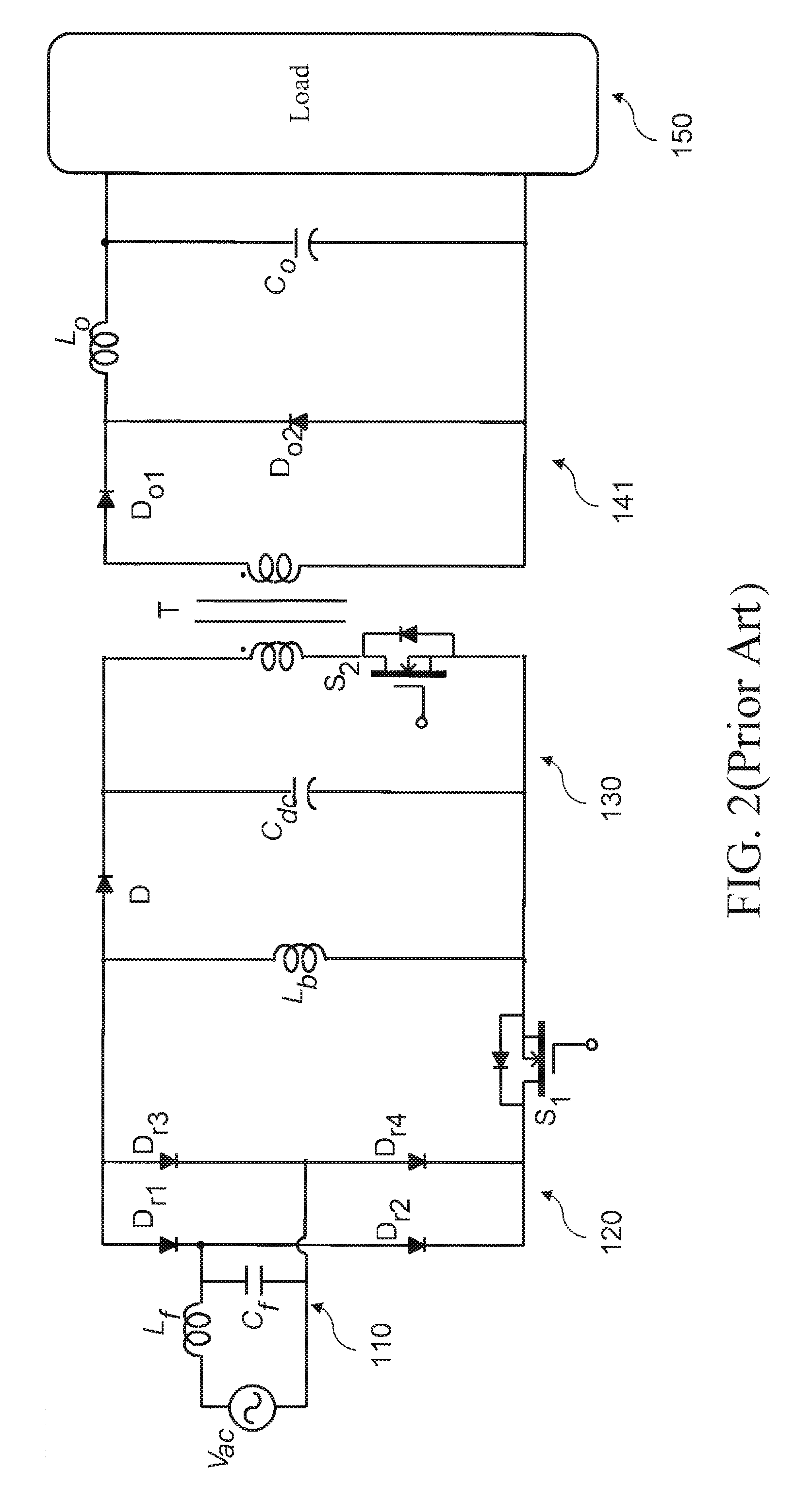
For the conventional two-stage architecture, two converter circuits with independent control are required, so the circuit cost is high; meanwhile, two power conversion stages also lead to lower circuit efficiency.
The higher the power is, the greater the peak current is, and the switching loss of the circuit also increases accordingly.
However, when the inductor operates in the CCM, a control circuit must detect the relations among the input voltage, the inductor current, and the output voltage in real time, so the circuit is complex.
Therefore, when the PFC circuit operates in the CCM, the PFC circuit is not suitable for being integrated with the second-stage converter.
However, when the flyback converter is used, since a leakage inductor of the transformer is large due to the operating principles and design of the circuit of the flyback converter, much energy is stored in the leakage inductor of the transformer.
At this time, a large surge is generated, causing a significant circuit loss, and thus reducing the circuit efficiency.
However, the active clamp technology requires adding at least one active switch and one capacitor, which increases the circuit cost and makes the control complex.

Method used


Image

  • Single-stage isolated high power factor ac/dc converter with leakage inductor energy recovery function
  • Single-stage isolated high power factor ac/dc converter with leakage inductor energy recovery function
  • Single-stage isolated high power factor ac/dc converter with leakage inductor energy recovery function

Examples


Embodiment Construction

[0036]The detailed features and advantages of the present invention are described below in great detail through the following embodiments, the content of the detailed description is sufficient for those skilled in the art to understand the technical content of the present invention and to implement the present invention accordingly. Based upon the content of the specification, the claims, and the drawings, those skilled in the art can easily understand the objectives and advantages of the present invention. The following embodiments are intended to describe the present invention in further detail, but not intended to limit the scope of the present invention in any way.

[0037]FIG. 3 shows a single-stage isolated high power factor AC / DC converter with a leakage inductor energy recovery function according to the present invention, which is applied to a flyback transformer for driving a load 250. In an exemplary embodiment, the AC / DC converter is formed by a filter circuit 210, a rectifi...


PUM


Abstract

A single-stage isolated high power factor AC / DC converter with a leakage inductor energy recovery function includes a buck-boost circuit, for step-down or step-down a power supply; a transformer, electrically connected to the buck-boost circuit, for transforming the stepped-down or stepped-up power supply; a switch, electrically connected to the buck-boost circuit; an input capacitor, electrically connected to the buck-boost circuit; and an output circuit, for outputting the power supply transformed by the transformer. When the switch is cut off, the buck-boost circuit provides an energy recovery path to return energy stored in a leakage inductor of the transformer to the input capacitor. The energy stored in the leakage inductor of the transformer in a flyback converter or a forward converter is returned to the input capacitor through the energy recovery path. The problem caused by the leakage inductor of the transformer is solved without using any additional element.

Description

CROSS-REFERENCE TO RELATED APPLICATIONS[0001]This non-provisional application claims priority under 35 U.S.C. §119(a) on Patent Application No(s). 097151789 filed in Taiwan, R.O.C. on Dec. 31, 2008, the entire contents of which are hereby incorporated by reference.BACKGROUND OF THE INVENTION[0002]1. Field of Invention[0003]The present invention relates to an AC / DC converter, and more particularly to a single-stage isolated high power factor AC / DC converter with a leakage inductor energy recovery function.[0004]2. Related Art[0005]A conventional AC / DC converter generally is the following structure: a boost converter, a buck converter, or a buck-boost converter is used as a first-stage power factor correction (PFC) circuit, and a forward converter or a flyback converter is used as a second-stage driving circuit, so as to achieve electrical isolation and convert an output voltage to a set level, thus providing a stable voltage for driving a load. For the conventional two-stage architec...

Claims


Application Information

Patent Timeline
IPC IPC(8): H02M3/335
CPCH02M1/34H02M3/33507H02M2001/346Y02B70/1491H02M1/4258H02M3/33523Y02B70/126H02M1/346Y02B70/10H02M3/28
Inventor LI, YAN CUN
Owner MACROBLOCK INC
Learn More