
Directional zone select interlock method

a directional zone and interlocking technology, applied in the field of relays and circuit breakers, can solve the problems of insufficient knowledge of the current magnitude of the fault, unnecessari delay of the tripping delay of the main circuit breaker, and insufficient knowledge of the fault location

Active Publication Date: 2010-07-01
ABB SPA
View PDF7 Cites 12 Cited by
  • Summary
  • Abstract
  • Description
  • Claims
  • Application Information

AI Technical Summary

Benefits of technology

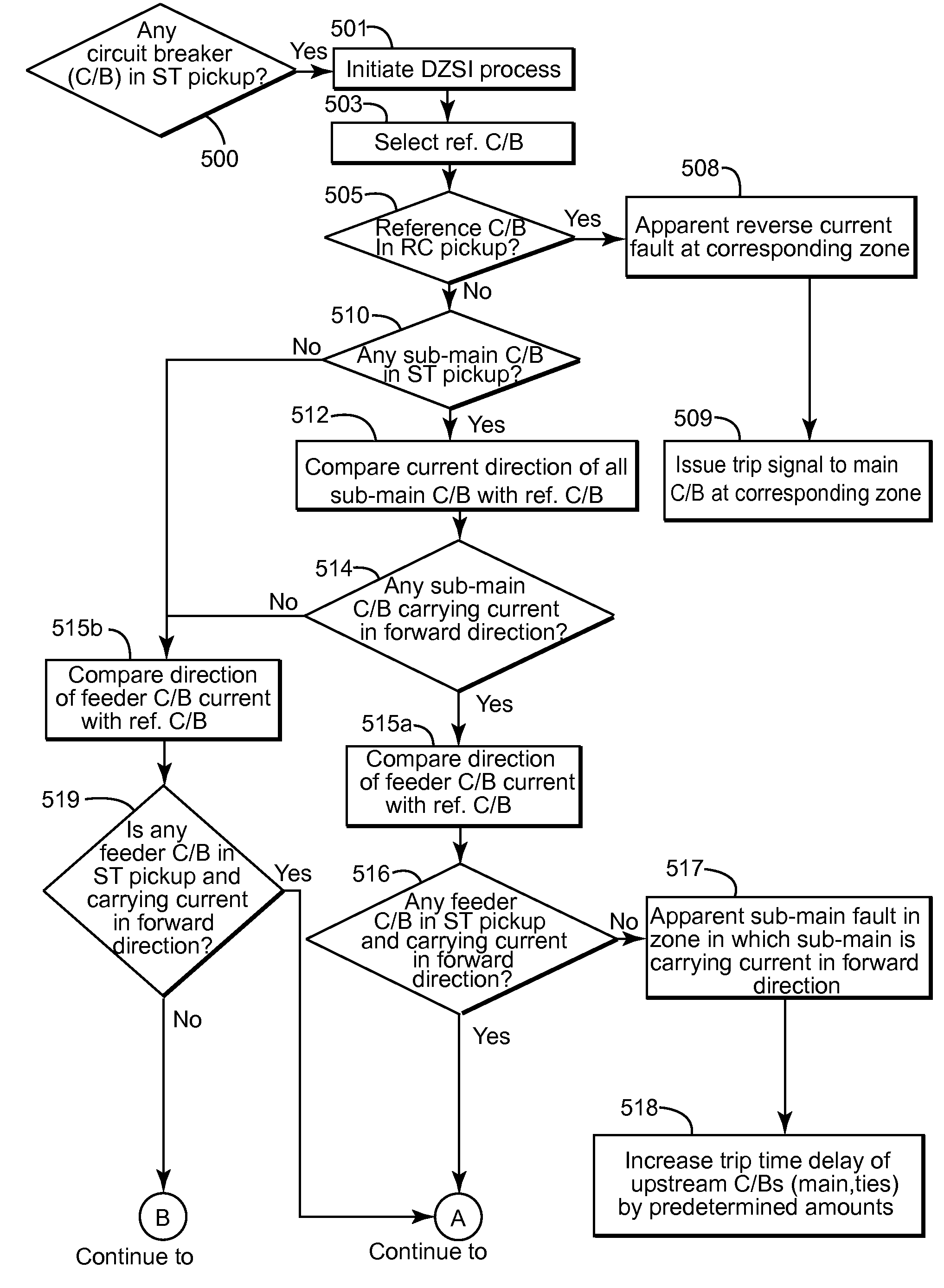
[0024]An improved method to detect and locate electrical faults is provided. A method of operating a circuit breaker in an electrical circuit configured with at least one of a first main circuit breaker at a first layer of circuit protection having a first direction of current flow, and at least one second circuit breaker downstream of said at least one first main circuit breaker having a second direction of

Problems solved by technology

In certain cases, the conventional ZSI technique unnecessarily delays the tripping delay of a main circuit breaker.
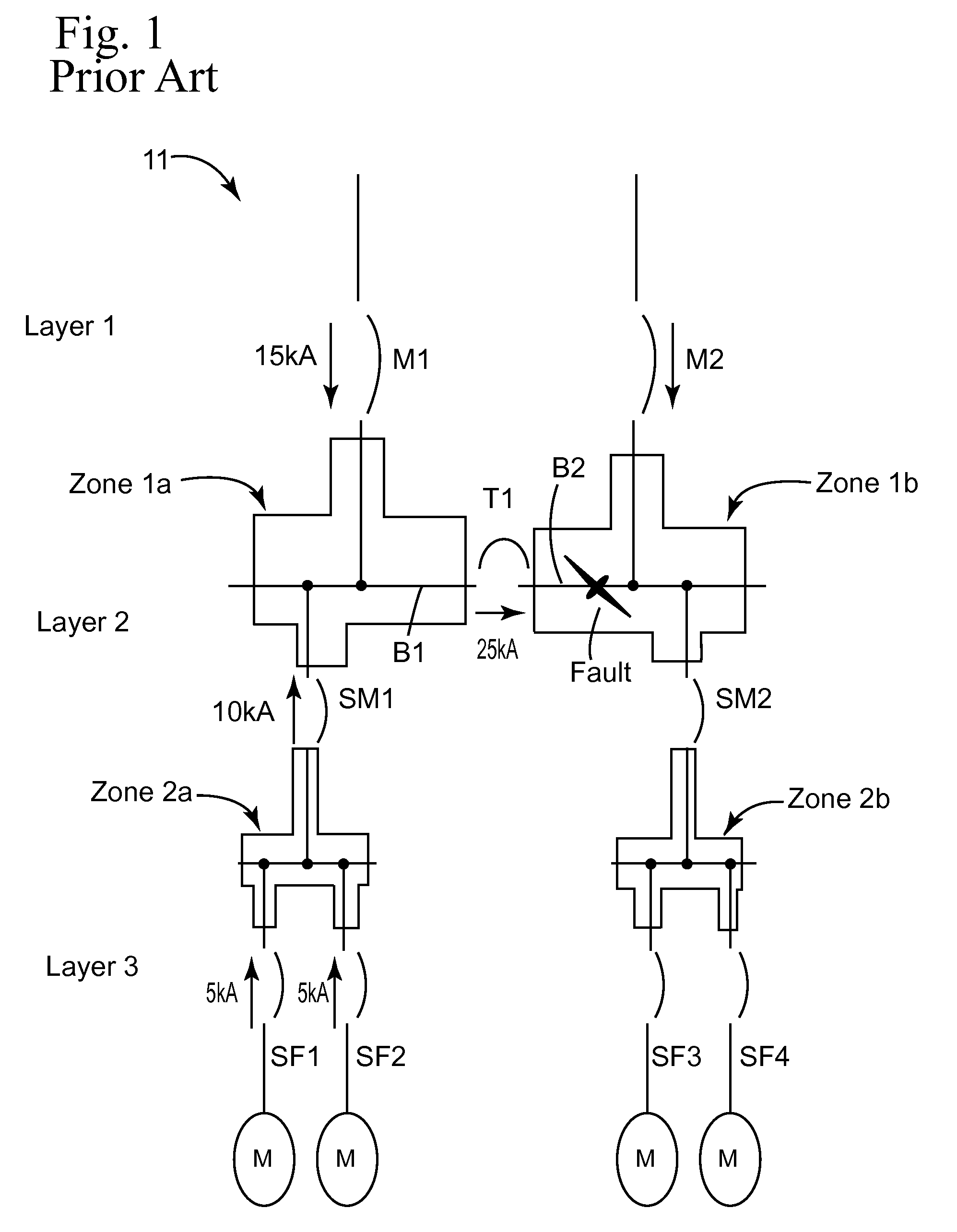
For example, a fault detection and isolation difficulty arises in the case of an electrical system fed by a first and a second separate power sources in parallel, and protected by a first and a second main circuit breakers connected in parallel, wherein a fault occurs between the first power source and its respective downstream main circuit breaker.
In such a case, mere knowledge of the fault current magnitude is not sufficient to identify the fault location, even when a conventional ZSI technique is used.
Consequently, the clearing time for the fault increases, and in some cases results in nuisance tripping of circuit breaker in a non-faulted part of the system.
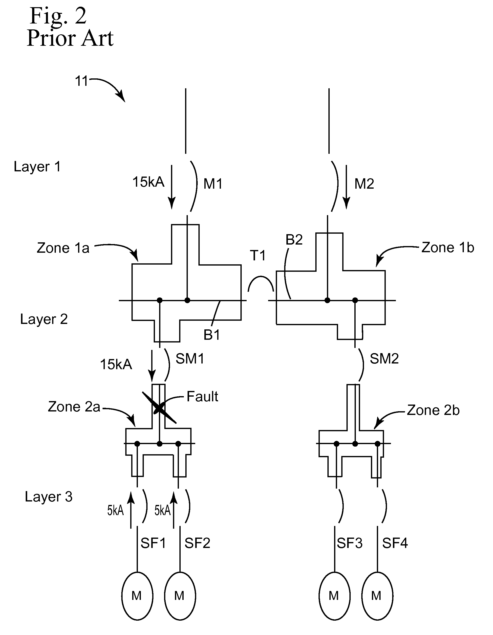
However, in some scenarios, the DZSI algorithm may also fail to correctly identify the location of fault.
Although the prior art method correctly identifies a bus fault in Zone 1b, the tripping of the tie circuit breaker T1 is delayed because of the detection of sub-main fault in Zone 2a, resulting in increased fault clearing time.

Method used


Image

  • Directional zone select interlock method
  • Directional zone select interlock method
  • Directional zone select interlock method

Examples


Embodiment Construction

[0032]As used herein, an element or function recited in the singular and proceeded with the word “a” or “an” should be understood as not excluding plural said elements or functions, unless such exclusion is explicitly recited. Furthermore, references to “one embodiment” of the claimed invention should not be interpreted as excluding the existence of additional embodiments that also incorporate the recited features.

[0033]This written description uses examples to disclose the invention, including the best mode, and also to enable any person skilled in the art to make and use the invention. The patentable scope of the invention is defined by the claims, and may include other examples that occur to those skilled in the art. Such other examples are intended to be within the scope of the claims if they have structural elements that do not differ from the literal language of the claims, or if they include equivalent structural elements with insubstantial differences from the literal langua...


PUM


Abstract

An improved method to detect and locate electrical faults is provided. A method of operating a circuit breaker in an electrical circuit configured with at least one of a first main circuit breaker at a first layer of circuit protection having a first direction of current flow, and at least one second circuit breaker downstream of said at least one first main circuit breaker having a second direction of current flow, and at least one third circuit breaker downstream of said at least one second circuit breaker having a third direction of current flow, wherein one of said at least one first, second, or third circuit breakers is in short time pick-up, is provided, and comprises steps to determine the location of the fault and adjust the trip time delay of the circuit breakers according to predetermined criteria.

Description

BACKGROUND[0001]1. Field of the Invention[0002]The field of the invention relates to relays and circuit breakers generally, and more particularly to certain new and useful advances in power system protective relays and circuit breakers of which the following is a specification, reference being had to the drawings accompanying and forming a part of the same.[0003]2. Discussion of Related Art[0004]Low-voltage power distribution systems are expected to deliver reliable power within constraints including, but not limited to, cost and size using available technology. Protective devices are chosen, installed, and adjusted to quickly operate, and selectively and reliably protect the low-voltage power distribution system. Time-based coordination and protection is the conventional basis for coordinating low-voltage power distribution systems.[0005]It will be understood that commonly used terms such as sub-main, feeder, sub-feeder, and branch are used to refer to circuit lines and their respe...

Claims


Application Information

Patent Timeline
IPC IPC(8): G01R31/08
CPCH02H3/38H02H7/262
Inventor SAWHNEY, ANUPAM VINODKUMARCHANGALI, SRIRAMNAREL, RADOSLAWVALDES, MARCELO ESTEBAN
Owner ABB SPA
Learn More