
Method for diagnosing abnormal plasma discharge, abnormal plasma discharge diagnostics system, and computer program

a plasma discharge and abnormal plasma technology, applied in the field of abnormal plasma discharge diagnosis, can solve the problems of difficult to grasp the measurement, damage to the substrate and components disposed inside the chamber, and the detachment of deposits stuck to the components inside the chamber, and achieve the effect of high accuracy in abnormal plasma discharge diagnosis

Active Publication Date: 2010-06-24
THE RITSUMEIKAN TRUST +1
View PDF5 Cites 8 Cited by
  • Summary
  • Abstract
  • Description
  • Claims
  • Application Information

AI Technical Summary

Benefits of technology

The present invention provides a method for accurately diagnosing abnormal plasma discharge without the need for multiple sensors in a plasma processing apparatus. The method involves obtaining time-series data that fluctuates in response to plasma conditions, deriving a value that represents determinism from the data, and determining if the plasma is under abnormal discharge conditions if the determinism value is below a certain threshold value. The method can be implemented using a single embedding vector and a realization frequency calculation, and can be used with various types of sensors such as AE, pressure, temperature, particle, current, and voltage sensors. The invention provides a more accurate and reliable method for diagnosing abnormal plasma discharge, which can help improve the efficiency and reliability of plasma processing.

Problems solved by technology

Since plasma is unstable, a difficulty is encountered in a measurement to grasp in what condition the plasma is—among others, in such processes as treat various elements, like processes in semiconductor manufacturing.
Such abnormal discharge causes damage to the substrate and components disposed inside the chamber.
The abnormal plasma discharge also causes detach of deposits stuck to a component inside the chamber, such as an upper electrode, and produces particles inside the chamber.
However, either of the above is of poor sensitivity and, among others, incapable of detecting minimal abnormal discharge.
However, as with the Patent Literature 2, in a method that enters time-series data in different band filters and detects the difference of that data by using a ratio of the maximum amplitude for each filter output, the abnormal plasma discharge is not identifiable in the case that the ultrasonic waves caused by abnormal discharge have the same frequency band and amplitude as the sound waves caused by opening / closing valves or as the sound waves in the vicinity of the device.
Thus, the abnormal discharge is not identifiable in conventional methods, because there may be no characteristic difference in the power spectrum even if the frequency power spectrum is estimated and the spectrum shape is compared under the normal conditions and under the abnormal discharge conditions.
Thus, the conventional time-series data analysis may not often show the difference between the time-series data clearly and quantitatively.

Method used


Image

  • Method for diagnosing abnormal plasma discharge, abnormal plasma discharge diagnostics system, and computer program
  • Method for diagnosing abnormal plasma discharge, abnormal plasma discharge diagnostics system, and computer program
  • Method for diagnosing abnormal plasma discharge, abnormal plasma discharge diagnostics system, and computer program

Examples


embodiment 1

[0107]Embodiments of the present invention will be described in detail below with reference to the drawings. It should be noted that the same and equivalent parts have the same code in the figures, and the explanations thereof are not repeated. An abnormal plasma discharge diagnostics system intended for a diagnosis of a plasma processing apparatus such as a semiconductor manufacturing device is exemplified and described below.

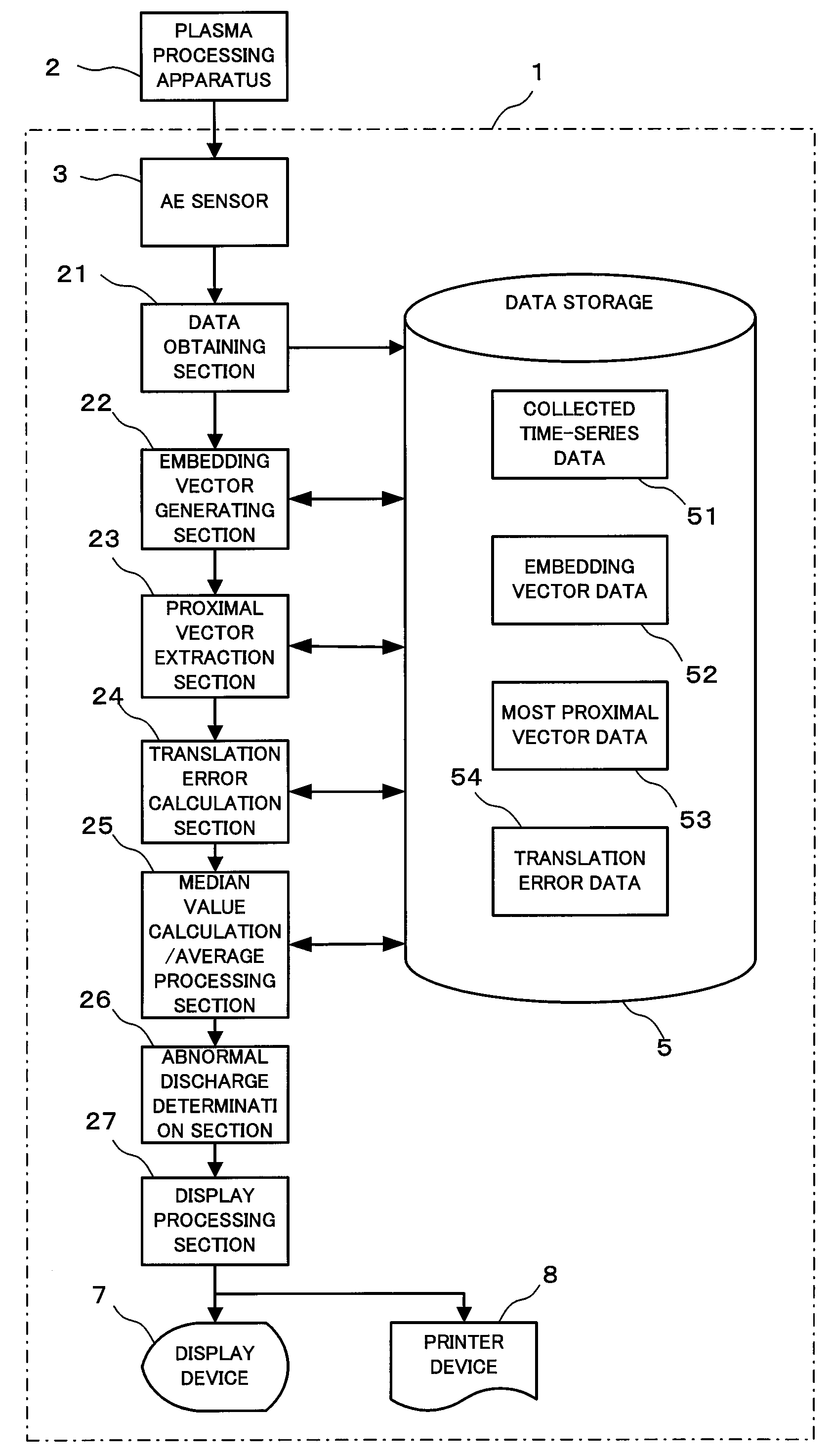
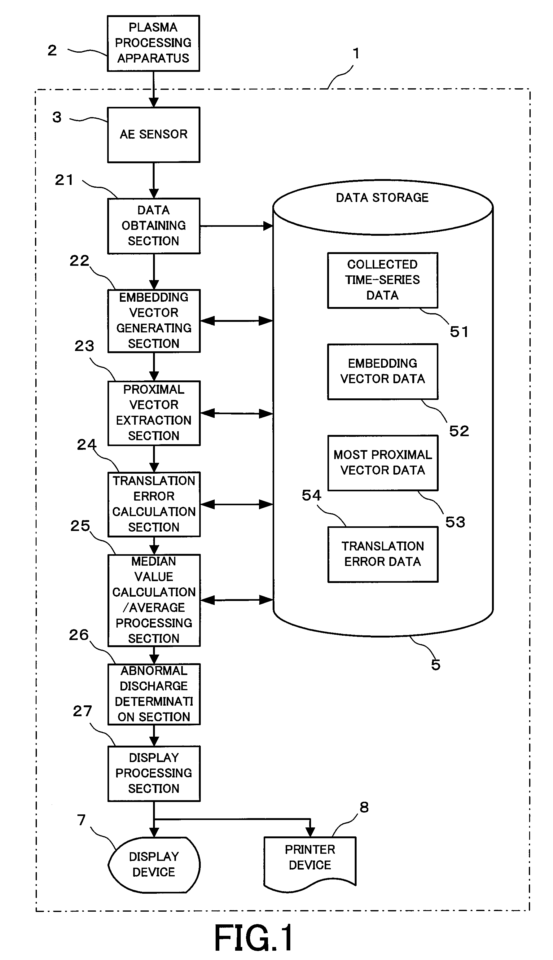
[0108]FIG. 1 is a block diagram showing a logical configuration of an abnormal plasma discharge diagnostics system 1, according to the first embodiment of the present invention. The abnormal plasma discharge diagnostics system 1 is comprised of an AE (Acoustic Emission) sensor 3, a data obtaining section 21, an embedding vector generation section 22, a neighbor vector extraction section 23, a translation error calculation section 24, a median value calculation / average processing section 25, a data storage 5, an abnormal discharge determination section 26, a di...

example 1

[0138]FIG. 5 is a graph showing an example of time-series data from an AE sensor of a plasma processing apparatus 2. In FIG. 5, A shows a part (active area) of the signals that is under the abnormal plasma discharge mode and S shows a part (silent area) of the signals that is under the normal conditions. For power spectrums for both the areas, the characteristic difference, for example, large or small spectrum in a certain frequency, is not seen. In the analysis of the power spectrum, it is difficult to clearly identify whether the plasma is under abnormal discharge conditions or normal conditions.

[0139]FIG. 6 is a graph showing an example of a translation error of data from AE sensor of a plasma processing apparatus 2. The results of calculating the translation errors for the signals from the AE sensor shown in FIG. 5 are shown in FIG. 6, having the embedding dimension and the translation error on a lateral axis and a longitudinal axis respectively. The graph A shown FIG. 6 corresp...

embodiment 2

[0142]Next, an abnormal plasma discharge diagnostics system 1 will be described below in the case that permutation entropy is employed as a value representing the determinism. FIG. 7 is a block diagram showing a logical configuration of an abnormal plasma discharge diagnostics system 1, according to the second embodiment of the present invention.

[0143]The abnormal plasma discharge diagnostics system 1 is comprised of an AE sensor 3, a data obtaining section 21, an embedding vector generation section 22, a realization frequency calculation section 28, a permutation entropy calculation section 29, an average processing section 30, a data storage 5, an abnormal discharge determination section 26, a display processing section 27, a display device 7, and a printer device 8. In this figure, the embedding vector generation section 22, the realization frequency calculation section 28, and the permutation entropy calculation section 29, and the average processing section 30, are combined to ...


PUM


Abstract

Provided are a data obtaining section (21) that obtains a time-series data fluctuating in accordance with the plasma conditions, a translation error calculation section (24) that calculates a determinism providing an indicator of whether the time-series data in the plasma are deterministic or stochastic, from the time-series data that have been obtained in the data obtaining unit (21), and an abnormal discharge determination section (26) that determines that the plasma is under the abnormal discharge conditions, in the case that the value representing the determinism calculated in the determinism derivation unit is less than or equal to a given threshold value, during the plasma generation. Examples of the value representing the determinism include translation error or permutation entropy. In the case the permutation entropy is used as a value representing the determinism, a permutation entropy calculation section is provided.

Description

TECHNICAL FIELD[0001]The present invention relates to a method for diagnosing abnormal plasma discharge, an abnormal plasma discharge diagnostics system, and a computer program.BACKGROUND ART[0002]Plasma processing apparatuses are in practical use. A plasma processing apparatus uses plasma to perform varying processes, including forming a thin film, edging, and reforming a substrate for e.g. a semiconductor wafer, a flat-panel display, and so forth. A typical operation performed by such apparatus is to introduce processing gas into the chamber, then apply a high-frequency electric power to the processing gas inside the chamber to produce plasma, and process substrate with the plasma. Since plasma is unstable, a difficulty is encountered in a measurement to grasp in what condition the plasma is—among others, in such processes as treat various elements, like processes in semiconductor manufacturing.[0003]Where the high-frequency electricity is applied inside a chamber in a plasma proc...

Claims


Application Information

Patent Timeline
Patent Type & Authority Applications(United States)
IPC IPC(8): G06F15/00
CPCH01J37/32935H05H1/0006H01J2237/0206
Inventor MIYANO, TAKAYAMATSUMOTO, TOSHIYUKIIKEUCHI, NAOKIMORIYA, TSUYOSHI
Owner THE RITSUMEIKAN TRUST
Learn More