
Apparatus and method of displaying an image

a technology of an image applied in the field of apparatus and a display device, can solve the problems of insufficient pva mode or ips mode to solve the side visibility weaknesses of the lcd device, insufficient enhancement of image quality, and complicated manufacturing processes, so as to improve the response time of the display device and a viewing angle, simplify the manufacturing process, and improve the effect of display quality

Inactive Publication Date: 2010-06-24
SAMSUNG DISPLAY CO LTD
View PDF5 Cites 3 Cited by
  • Summary
  • Abstract
  • Description
  • Claims
  • Application Information

AI Technical Summary

Benefits of technology

[0007]Example embodiments of the present invention provide a method of displaying an image capable of improving display quality.
[0019]According to the present invention, an image is displayed by using blue-phase liquid crystal, so that a manufacturing process of the display apparatus may be simplified. Moreover, the response time of a display apparatus and a viewing angle may be enhanced, so that display quality may be improved. Furthermore, a bluish phenomenon of blue-phase liquid crystal may be prevented, so that a contrast ratio may be increased. Furthermore, color reproducibility in accordance with a grayscale may be enhanced, so that display quality may be enhanced.

Problems solved by technology

The alignment film in the LCD device requires many processes such as a spreading process, a rubbing process, a light alignment process, etc., that complicate the manufacturing processes.
However, to date, the PVA mode or the IPS mode have been insufficient to solve the side visibility weaknesses of the LCD device.
The response time of the liquid crystal may not be sufficiently fast in a device, such as a television, to embody a moving image, resulting a problem in that image quality may not be enhanced.

Method used


Image

  • Apparatus and method of displaying an image
  • Apparatus and method of displaying an image
  • Apparatus and method of displaying an image

Examples


Embodiment Construction

[0049]The present invention is described more fully hereinafter with reference to example embodiments shown in the accompanying drawings. The present invention may, however, be embodied in many different forms and should not be construed as limited to the example embodiments set forth herein. Rather, these example embodiments are provided so that this disclosure will be thorough and complete, and will fully convey the scope of the present invention to those skilled in the art. In the drawings, the sizes and relative sizes of layers and regions may be exaggerated for clarity.

[0050]It will be understood that when an element or layer is referred to as being “on,”“connected to” or “coupled to” another element or layer, it can be directly on, connected or coupled to the other element or layer or intervening elements or layers may be present. In contrast, when an element is referred to as being “directly on,”“directly connected to” or “directly coupled to” another element or layer, there ...


PUM

PropertyMeasurementUnit
electric fieldaaaaaaaaaa
optical anisotropyaaaaaaaaaa
birefringenceaaaaaaaaaa

Abstract

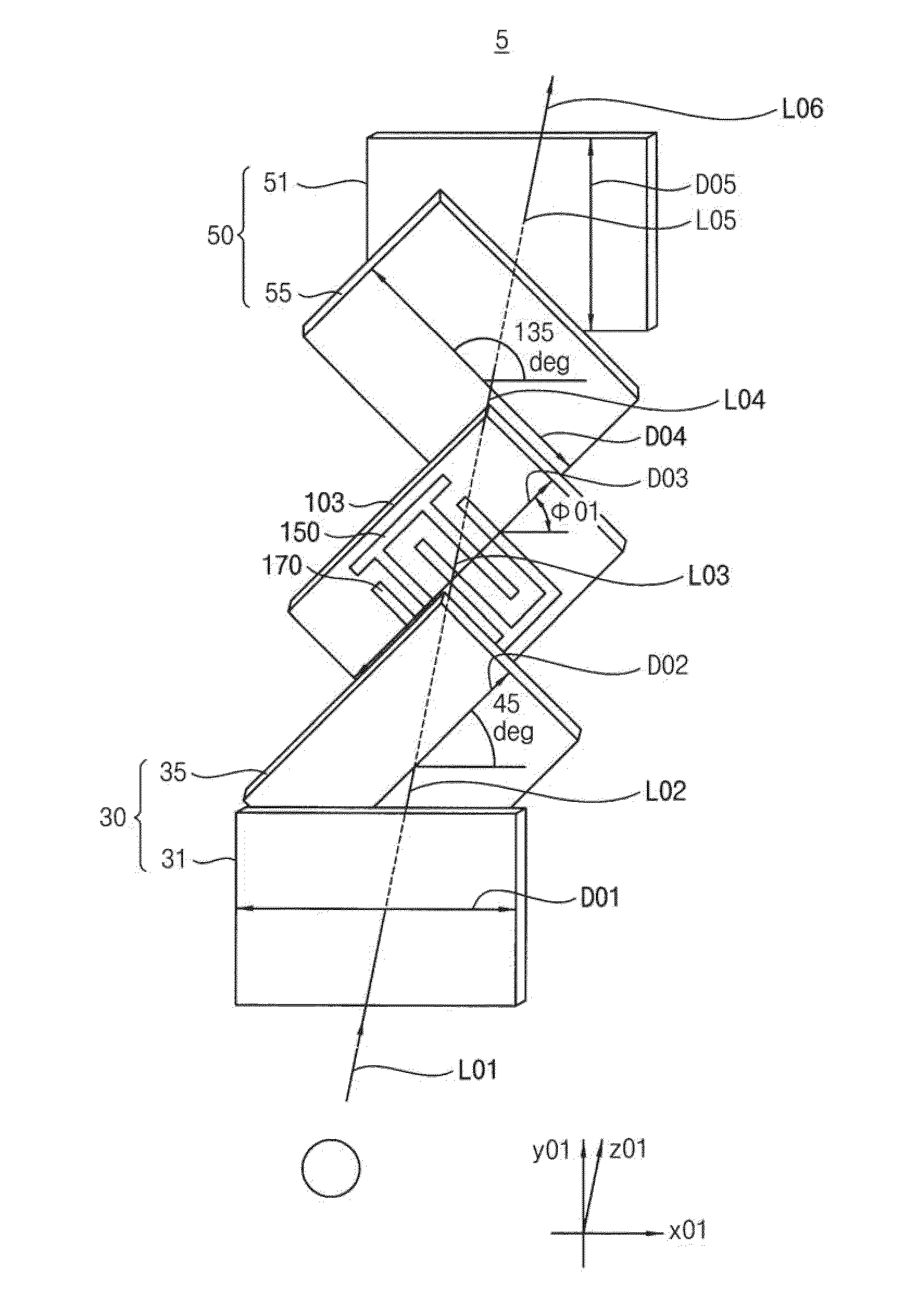
A display apparatus includes a display panel, a first polarization part, and a second polarization part. The display panel includes an array substrate, an opposite substrate and an electro-optical material layer disposed between the array substrate and the opposite substrate. The electro-optical material layer reflects first circularly polarized light having a wavelength of a predetermined range and transmits second circularly polarized light having a phase difference with the first circularly polarized light. The first polarization part faces a rear face of the array substrate and converts incident light of the rear face into the first circularly polarized light. The second polarization part faces a front face of the opposite substrate and blocks the first circularly polarized light reflected from the electro-optical material layer and transmits the second circularly polarized light transmitted through the electro-optical material layer.

Description

PRIORITY STATEMENT[0001]This application claims priority under 35 U.S.C. §119 to Korean Patent Application No. 2008-129762, filed on Dec. 19, 2008 in the Korean Intellectual Property Office (KIPO), the contents of which are herein incorporated by reference in their entirety.BACKGROUND[0002]1. Field of the Invention[0003]Example embodiments of the present invention relate to an apparatus and a method of displaying an image. More particularly, example embodiments of the present invention relate to an apparatus and a method of displaying an image capable of improving display quality.[0004]2. Description of the Related Art[0005]Generally, when compared to a cathode ray tube (CRT), a liquid crystal display (LCD) device is slimmer, lighter, consumes less power, and is more widely used. The LCD device includes a liquid crystal panel and polarization plates respectively disposed at a rear face and a front face of the liquid crystal panel. The liquid crystal panel may include an alignment fi...

Claims


Application Information

Patent Timeline
Patent Type & Authority Applications(United States)
IPC IPC(8): G02F1/1335G02B27/26G02B30/25
CPCG02F1/134363G02F1/13718G02F2203/64G02F2001/133541G02F2001/13775G02F1/13731G02F1/133541G02F1/13775G02F1/13G02F1/1335
Inventor PARK, JAE-HONGKWON, OH-JEONGPARK, HONG-JOLEE, HYEOK-JINYUN, SUNG-JAEKIM, HEE-SEOP
Owner SAMSUNG DISPLAY CO LTD
Learn More