
System and method for monitoring and controlling stator winding temperature in a de-energized ac motor

a stator winding and de-energized technology, applied in the direction of motor/generator/converter stopper, dynamo-electric converter control, instruments, etc., can solve the problems of premature damage to the winding insulation, certain amount of time is typically required before the motor can be restarted, and the effect of adding more resistance to the motor

Active Publication Date: 2010-06-24
EATON CORP
View PDF21 Cites 56 Cited by
  • Summary
  • Abstract
  • Description
  • Claims
  • Application Information

AI Technical Summary

Benefits of technology

[0009]It would therefore be desirable to design an accurate, non-intrusive method for monitoring and controlling stato...

Problems solved by technology

If the motor is tripped by overload relays, a certain amount of time is typically required before the motor can be restarted.
Either this recovery time may be too conservative and production time is lost, or the recovery time may be too short and the incomplete cooling accumulates after each shutdown, potentially leading to premature damage to the winding insulation due to overheating.
When electric machines are shut down, the stator winding temperature may fall below the ambient temperature, causing moisture condensation on the stator windings, brushes, and other compartments.
This condensation can be detrimental to the life of the motor in certain applications.
However, due to the thermal parameter variation and the difficulty of thermal parameter identification, the accuracy of these methods may fall outside acceptable ranges.
Besides, due to possible changes in cooling conditions, the thermal parameters are not always constant, and may need to be identified for each motor under each specific cooling condition.
This, however, leaves one phase unheated, or reliant on inductive heat.
Also, because the stator resistance is relatively small, a large voltage and current input is typically needed to heat the motor.
This large voltage and current input may reduce the life of the stator winding.

Method used


Image

  • System and method for monitoring and controlling stator winding temperature in a de-energized ac motor
  • System and method for monitoring and controlling stator winding temperature in a de-energized ac motor
  • System and method for monitoring and controlling stator winding temperature in a de-energized ac motor

Examples


Embodiment Construction

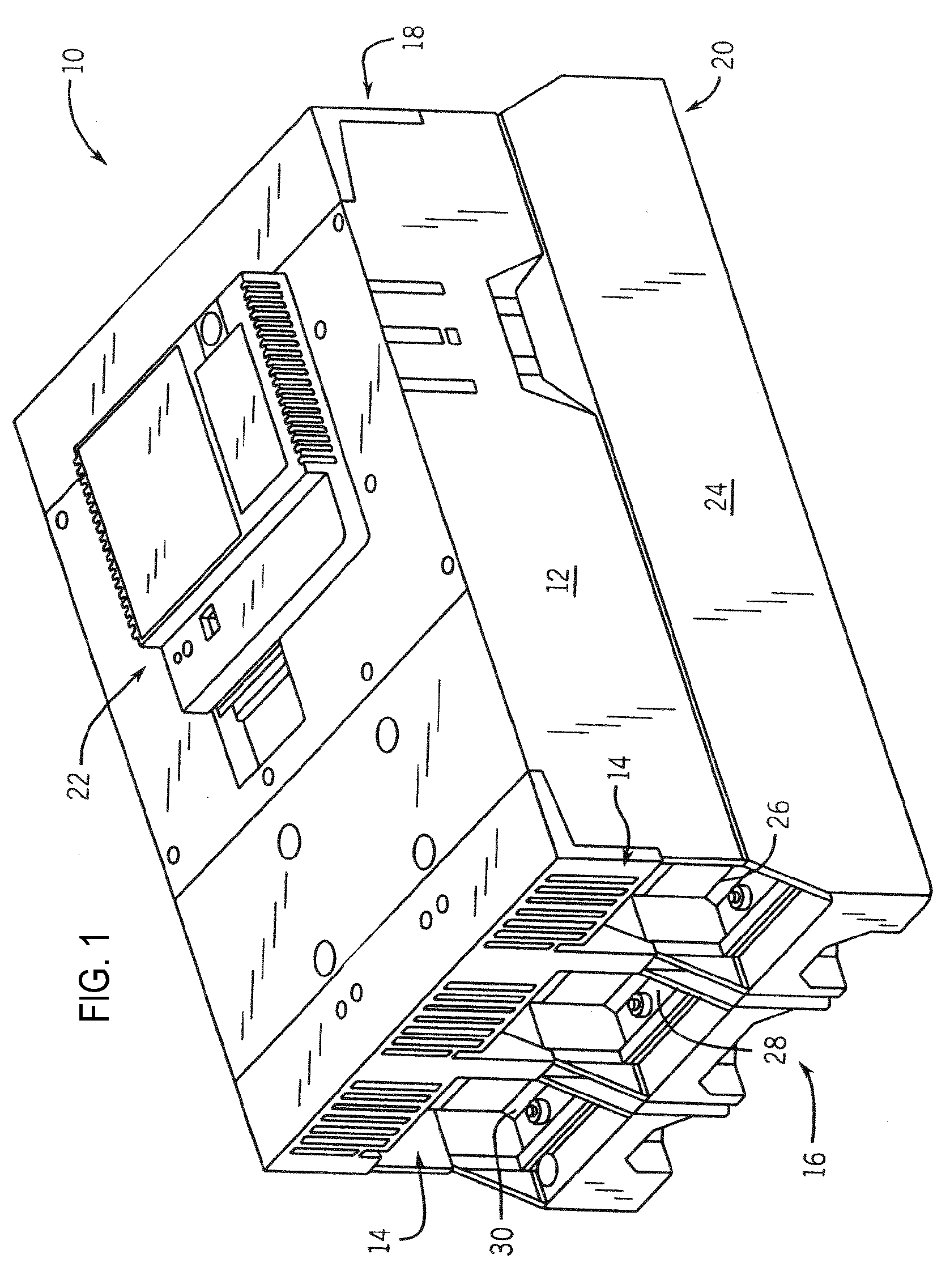
[0026]The embodiments of the invention set forth herein relate to a system and method for remote and sensorless stator winding resistance estimation for monitoring the temperature of and providing heat to alternating current (AC) motors. In one embodiment, the invention is implemented in a motor control device or a soft-starter, for example. A soft-starter 10 is shown in FIG. 1 and includes a cover assembly 12 having air inlets 14 on a motor connection end, or load end 16. Similar air outlets 18 are located on a power source end, or line end 20 of the soft-starter 10. The cover assembly 12 also houses an electronic controller 22. Soft-starter 10 also includes a base assembly 24 to house each of switch assemblies 26, 28, 30. Each of the switch assemblies 26-30 is identical in construction for a given soft-starter 10 and corresponds to a phase of a multi-phase input to a multi-phase AC motor.

[0027]According to one aspect of the invention, the activation of a pair of switches in the sw...


PUM


Abstract

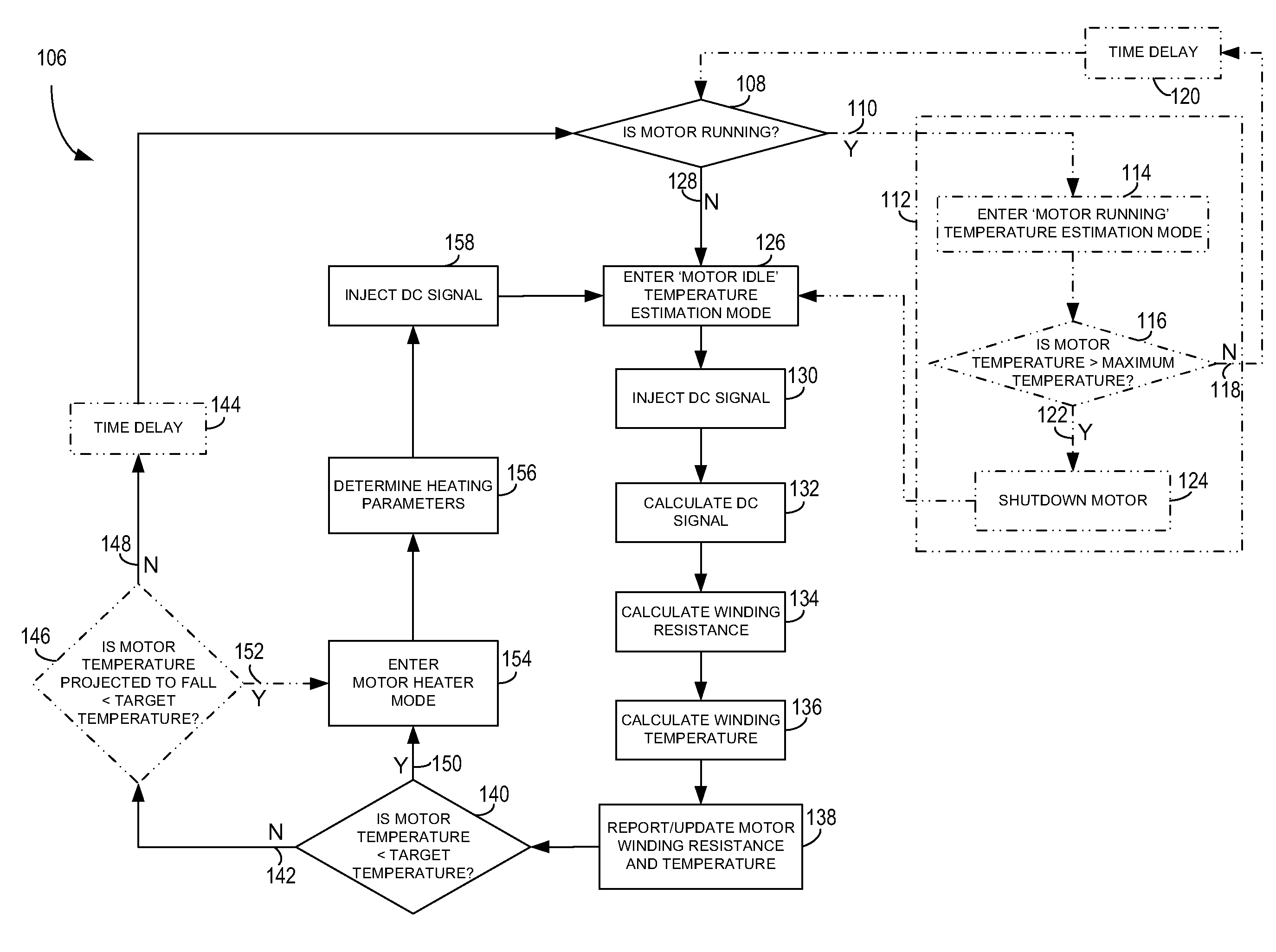
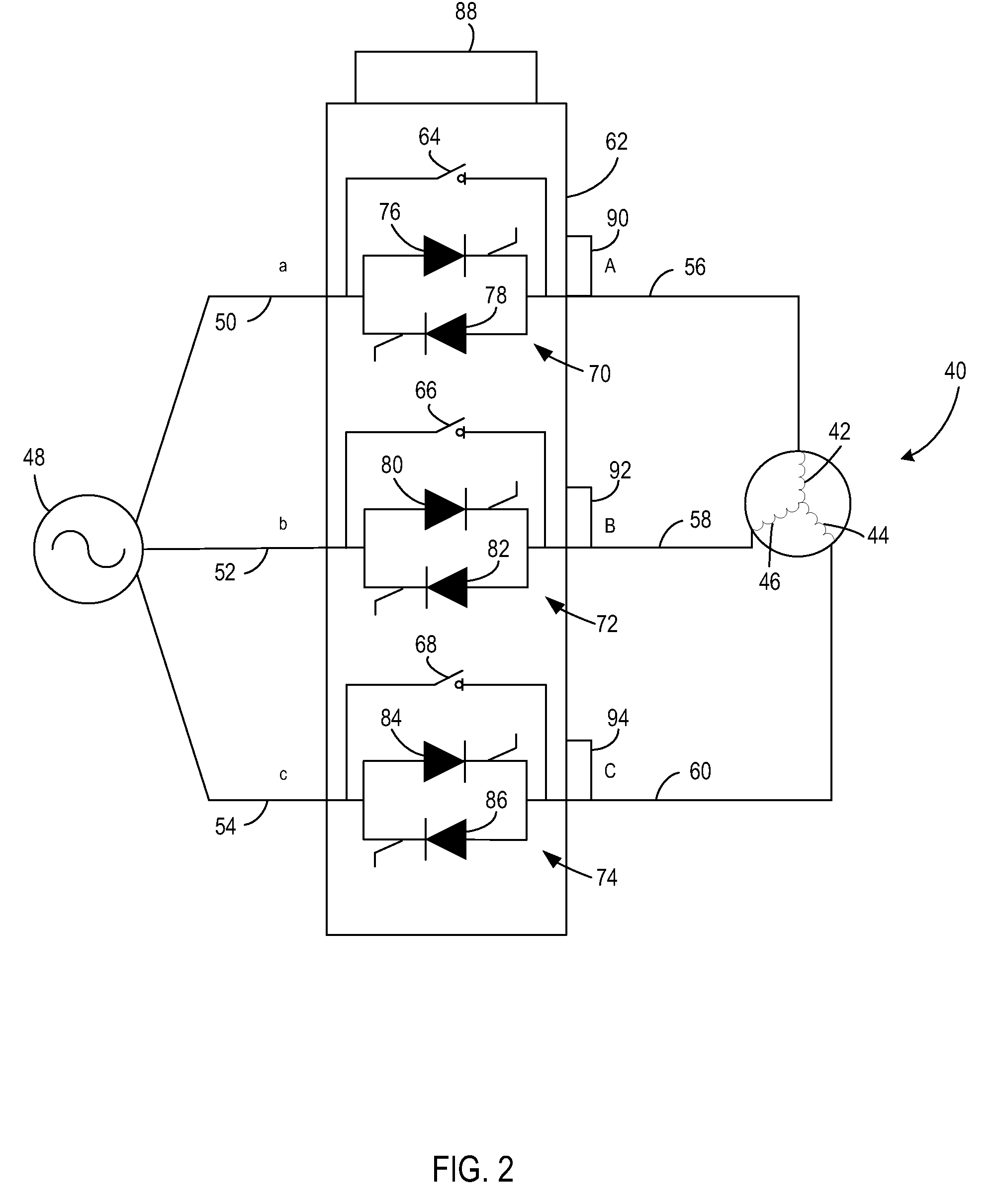
A system and method for measuring and controlling stator winding temperature in an AC motor while idling is disclosed. The system includes a circuit having an input connectable to an AC source and an output connectable to an input terminal of a multi-phase AC motor. The circuit further includes a plurality of switching devices to control current flow and terminal voltages in the multi-phase AC motor and a controller connected to the circuit. The controller is configured to activate the plurality of switching devices to create a DC signal in an output of the motor control device corresponding to an input to the multi-phase AC motor, determine or estimate a stator winding resistance of the multi-phase AC motor based on the DC signal, and estimate a stator temperature from the stator winding resistance. Temperature can then be controlled and regulated by DC injection into the stator windings.

Description

GOVERNMENT LICENSE RIGHTS[0001]The present invention was made at least in part with Government support under Contract No. DE-FC36-04GO14000, awarded by the United States Department of Energy. The Government may have certain rights in the invention.BACKGROUND OF THE INVENTION[0002]The present invention relates generally to alternating current (AC) motors and, more particularly, to a system and method for determining stator winding resistance for thermal protection of AC motors.[0003]Thermal protection is an important aspect in the monitoring of motor conditions, as motor failures can often be related to thermal stress on stator winding insulation. It is commonly assumed that the motor's life is reduced by 50% for every 10° C. increase in temperature above an acceptable stator winding temperature limit.[0004]Thermal protection of AC motors is important not only to running motors, but also to de-energized motors. In many applications, the AC motor is periodically de-energized to allow ...

Claims


Application Information

Patent Timeline
IPC IPC(8): H02P29/02H02H7/08
CPCH02P29/0055H02P23/14H02P29/64
Inventor LU, BINLUEBKE, CHARLES JOHNHABETLER, THOMAS G.ZHANG, PINJIABECKER, SCOTT K.
Owner EATON CORP
Learn More