Shield layer plus refrigerated backside cooling for planar motors

a planar motor and backside cooling technology, applied in the field of semiconductor processing, can solve the problems of generating a significant amount of heat for planar motors used in semiconductor processing equipment such as photolithography apparatuses, adversely affecting the accuracy of photolithography processes, and affecting the positioning accuracy of exposure apparatuses, etc., and achieves the effect of less heat and more hea

Inactive Publication Date: 2010-06-24
NIKON CORP
View PDF8 Cites 18 Cited by
  • Summary
  • Abstract
  • Description
  • Claims
  • Application Information

AI Technical Summary

Benefits of technology

[0010]In one embodiment, the at least one coil includes coils that are intermittently active, or that produce different amounts of heat. In such an embodiment, a first coolant supply is configured to provide a first coolant to the coil(s) producing more heat and a second coolant to the coil(s) producing less heat.
[0011]According to another aspect of the present invention, a method of cooling a motor that has at least one coil with a first side and a backside, and a cover plate positioned at a distance from the first side of the at least one coil, includes providing at least one coolant to the at least one coil. The coolant is provided fr

Problems solved by technology

An increase in heat may adversely affect the accuracy of a photolithography process.
For example, a positioning accuracy of an exposure apparatus may be compromised.
Planar motors which are used in semiconductor processing equipment such as a photolithography apparatus often generate a significant amount of heat.
By way of example, when a planar motor moves, the coils in the planar motor generally generate a relatively large amount of heat.
When the heat generated by a planar motor reaches critical components in semiconductor processing equipment, the performance of those components and, hence, the semiconductor processing equipment may be adversely impacted.
That is, some components in semiconductor processing equipment are temperature-sensitive an

Method used


Image

  • Shield layer plus refrigerated backside cooling for planar motors
  • Shield layer plus refrigerated backside cooling for planar motors
  • Shield layer plus refrigerated backside cooling for planar motors

Examples


Embodiment Construction

[0022]Example embodiments of the present invention are discussed below with reference to the various figures. However, those skilled in the art will readily appreciate that the detailed description given herein with respect to these figures is for explanatory purposes, as the invention extends beyond these embodiments.

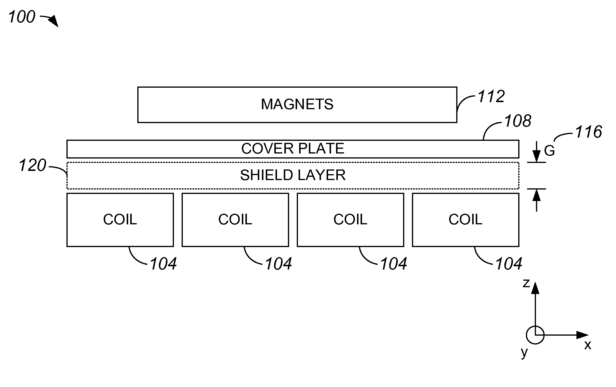
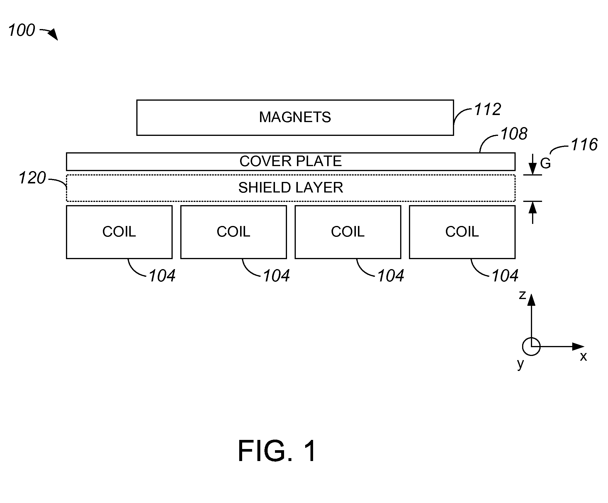
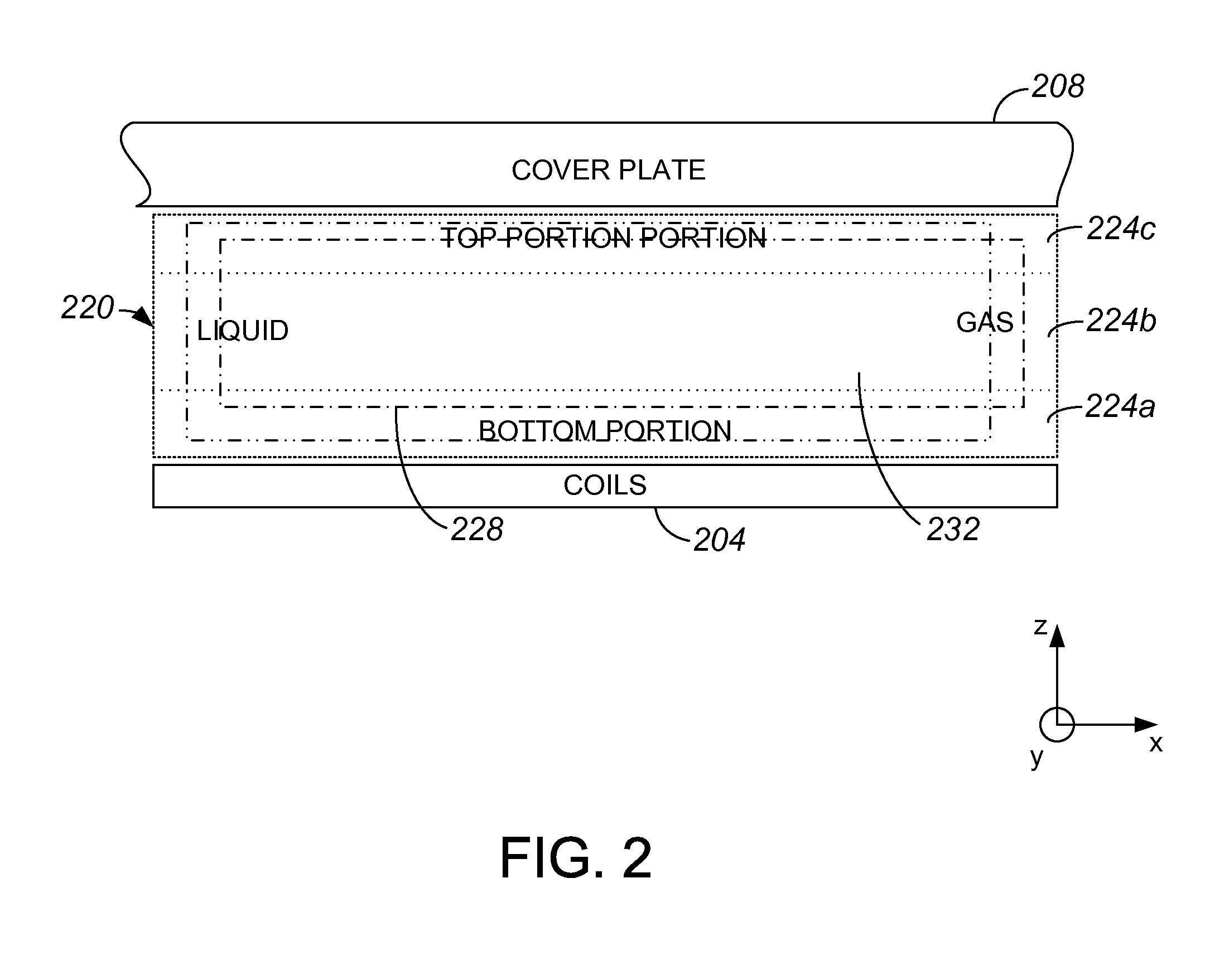
[0023]To assure the performance of semiconductor processing equipment, planar motors associated with the semiconductor processing equipment are cooled. Because of space constraints in a planar motor, as well as other factors such as power level requirements, maintaining a constant temperature against a cover plate of the planar motor is generally difficult. By creating a shield layer within a planar motor that has a mixture of liquid and gas, a substantially constant temperature may be maintained at a top portion of the shield layer, e.g., at a portion of the shield layer which abuts or otherwise effectively comes into contact with a cover plate. Such a two-phase shiel...


PUM


Abstract

According to one aspect of the present invention, a motor arrangement includes at least one coil, a cover plate, and a shield layer. The at least one coil has a first side and a second side. The cover plate is positioned substantially over the first side of the at least one coil at a distance from the at least one coil. The shield layer is positioned between the first side of the at least one coil and the cover plate, and has a top surface. The top surface contacts the cover plate, and includes a liquid and a gas that form a mixture and cause the top surface to have a substantially constant temperature.

Description

CROSS-REFERENCE TO RELATED APPLICATION[0001]The present invention claims priority of U.S. Provisional Patent Application No. 61 / 140,042, filed Dec. 22, 2008, which is incorporated herein by reference in its entirety.BACKGROUND OF THE INVENTION[0002]1. Field of the Invention[0003]The present invention relates generally to semiconductor processing.[0004]2. Description of the Related Art[0005]Current supplied to motors used in photolithography equipment, e.g., motors included in a reticle stage assembly and / or a wafer stage assembly, generate heat that is subsequently transferred to a surrounding environment. An increase in heat may adversely affect the accuracy of a photolithography process. For example, a positioning accuracy of an exposure apparatus may be compromised.[0006]Planar motors which are used in semiconductor processing equipment such as a photolithography apparatus often generate a significant amount of heat. By way of example, when a planar motor moves, the coils in the ...

Claims


Application Information

Patent Timeline
IPC IPC(8): H02K9/20H02K41/03
CPCG03F7/70758G03F7/70858H02K9/20H02K41/031H02K2201/18H02K9/19
Inventor COOPER, ALEXANDERCOAKLEY, SCOTTWATSON, DOUGLAS C.PHILLIPS, ALTON H.KESWANI, GAURAVBINNARD, MICHAEL B.
Owner NIKON CORP
Why Eureka
Try Eureka