Target material removal using rare earth metals

Inactive Publication Date: 2010-06-24
MOLYCORP MINERALS
View PDF104 Cites 51 Cited by
  • Summary
  • Abstract
  • Description
  • Claims
  • Application Information

AI Technical Summary

Benefits of technology

[0014]The insoluble target material-containing composition is typically in the form of precipitate that can be removed as a solid. Preferably, the insoluble target material-containing composition has at least about 0.01 wt. %, even more preferably at least about 0.1 wt. %, and even more preferably ranges from about 5 to about 50 wt. % of the target material. The target material is commonly in the form of an oxygen-containing anion with an oxyanion being illustrative. The soluble fixing agent, or precipitant, can be supported by a suitable carrier or be unsupported. The ability to form the insoluble target material-containing composition in the form of a solid comprising a relatively high concentration of the target material can greatly reduce the volume of the insoluble target material-containing composition requiring disposal, thereby reducing disposal costs.
[0039]The second salt additive, in a preferred formulation, contains aluminum in the +3 oxidation state. The first and second salt additives can provide significant reductions in the amount of rare earths required to remove selected target materials, particularly arsenic.
[0054]It has been discovered that interferors, particularly phosphates, fluorides, carbonates, silicates, and vanadate can readily form compositions with or otherwise impede target material removal by the rare earth fixing agent, thereby consuming unnecessarily the fixing agent when it is desired to remove target materials, such as arsenic. Removing the competing or otherwise obstructing oxyanion interferors prior to fixing agent contact with the target material can reduce fixing agent consumption.
[0059]The present invention can include a number of advantages depending on the particular configuration. The process of the present invention can remove variable amounts of target materials as needed to comply with application and process requirements. For example, the target material removal process can remove high concentrations of target materials to produce a treated solution having no more than about 500 ppm, in some cases no more than about 100 ppm, in other cases no more than about 50 ppm, in still other cases no more than about 20 ppb, and in still other cases no more than about 1 ppb target material. The insoluble rare earth / target material product can be qualified as non-hazardous waste. The target material removal process can be relatively insensitive to pH. The disclosed process can effectively fix target materials, particularly arsenic, from solutions over a wide range of pH levels, as well as at extremely high and low pH values. In contrast to many conventional target material removal technologies, this capability can eliminate the need to alter and / or maintain the pH of the solution within a narrow range when removing the target material. Moreover, where the aqueous solution is produced from the remediation of an arsenic-bearing material, it adds flexibility because the selection of materials and processes for leaching arsenic from an arsenic-bearing material can be made without significant concern for the pH of the resulting arsenic-containing solution. Further still, elimination of the need to adjust and maintain pH while fixing arsenic from an arsenic-containing solution can provide significant cost advantages. The target material removal process can also be relatively insensitive to target material concentration. The process can remove relatively low and high levels of target materials, particularly arsenic, from aqueous streams. The process can be a robust, versatile process.

Problems solved by technology

Many of the harmful metals have multiple oxidation states, which can complicate their removal.
Most technologies for harmful metal removal are hindered by the difficulty of removing a number of these metals.
Harmful metal removal may be further complicated by co-occurrence with valuable metals.
This precipitation method requires a series of pH adjustments to form and, in many applications, produces an excessively large volume of, the ferric arsenate precipitate.
In some embodiments, the target material will be present in a reduced oxidation state and this condition might be undesirable.
(a) receiving a target material-containing stream, the target material-containing stream comprising an interferor, the interferor adversely impacting (e.g., impairing the level, extent, and / or degree of) rare earth precipitation of the target material;
(b) removing at least most of the interferor from the target material-containing stream to form a treated stream comprising at least most of the target material; and
(c) thereafter contacting the treated stream with a rare earth fixing agent to precipitate most of the target material from the treated solution.
It has been discovered that interferors, particularly phosphates, fluorides, carbonates, silicates, and vanadate can readily form compositions with or otherwise impede target material removal by the rare earth fixing agent, thereby consuming unnecessarily the fixing agent when it is desired to remove target materials, such as arsenic.

Method used


Image

  • Target material removal using rare earth metals
  • Target material removal using rare earth metals
  • Target material removal using rare earth metals

Examples


example 1

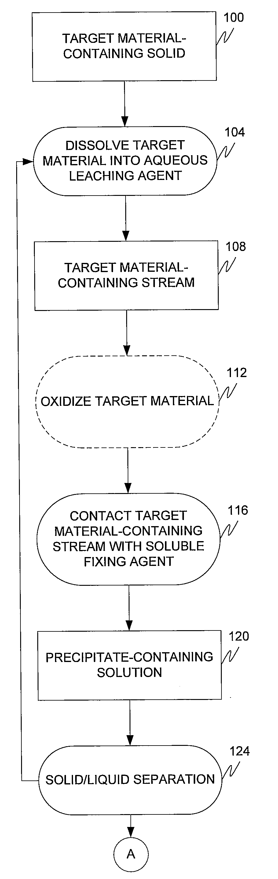
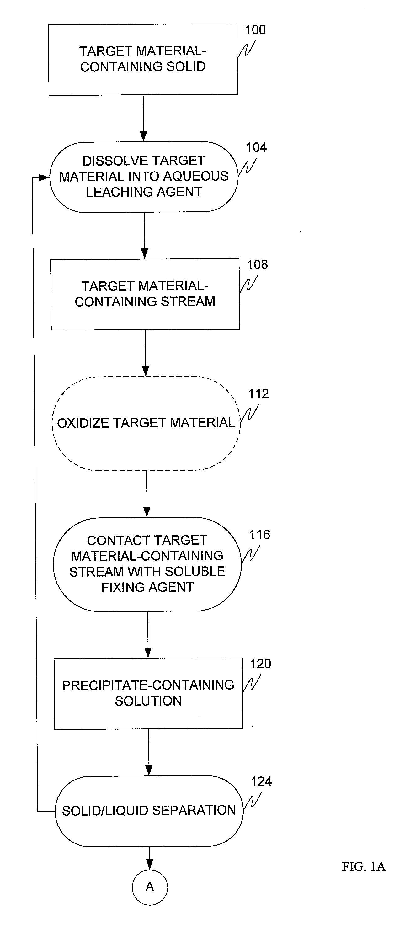
[0144]A set of tests were conducted to determine a maximum arsenic loading capacity of soluble cerium (III) chloride CeCl3 in an arsenic-containing stream 108 to reduce the arsenic concentration to less than 50 ppm. As shown by Table 1, the arsenic-containing streams 108 (hereinafter alkaline leach solutions) tested had the following compositions:

TABLE 1VolumeTestof DINa2CO3Na2SO4Na2HAsO4—7H2ONumber(mL)(g)(g)(g)As g / L1500108.8751.0410.52500108.8752.08213500108.8754.16424500108.8756.24735500108.8758.32946500108.87510.41157500108.87512.4936

[0145]The initial pH of the seven alkaline leach solutions was approximately pH 11, the temperatures of the solutions were approximately 70 to 80° C., and the reaction times were approximately 30 minutes.

[0146]Seven alkaline leach solutions were made with varying arsenic (V) concentrations, which can be seen in Table 1 above. Each solution contained the same amount of sodium carbonate (20 g / L) and sodium sulfate (17.75 g / L). In a first series of tes...

example 2

[0153]In another experiment, 40 grams of cerium (IV) dioxide particles were loaded into a 1-inch column giving a bed volume of approximately 50 ml. The cerium dioxide bed had an arsenic-containing process stream [75% As(V), 25% As (III)] flowed through the bed and successfully loaded the media with approximately 44 mg of arsenic per gram CeO2 or with approximately 1,700 mg of arsenic total added to the column. Following this, the arsenic loaded cerium dioxide bed had the equivalent of six bed volumes of 5% NaOH solution passed through the bed, at a flow rate of 2 mL / min. This solution released approximately 80% of the 44 mg of arsenic per gram CeO2. Subsequently, the same cerium media was then treated again with the arsenic contaminated process stream [75% As(V), 25% As(III)], loading the media with another 25 mg of arsenic per gram CeO2 or with another 1,000 mg of arsenic. This experiment demonstrates how to regenerate, and thereby prolong the life of, the insoluble fixing agent an...

example 3

[0154]A test was performed to remove residual rare earth fixing agents from an alkaline leach solution.

[0155]Fifteen grams of table salt (NaCl) were added to 150 mL of alkaline leach solution that contained residual cerium from cerium nitrate addition. Table 6 shows the beginning (control) and post-salt concentrations in the alkaline leach solution:

TABLE 3AsCeSample(ppm)(ppm)Control2204700Salt Addition250270

[0156]As can be seen from this Table 3, 94% of the residual cerium has been removed.


PUM

PropertyMeasurementUnit
Acidityaaaaaaaaaa
Acidityaaaaaaaaaa
Acidityaaaaaaaaaa

Abstract

The present invention is directed to the removal of one or more selected target materials from various streams using a rare earth metal-containing fixing agent.

Description

CROSS REFERENCE TO RELATED APPLICATION[0001]The present application claims the benefits of U.S. Provisional Application Ser. No. 61 / 113,435, filed Nov. 11, 2008, entitled “Arsenic Removal Using Rare Earth Metals”; U.S. Provisional Application Ser. No. 61 / 179,622, filed May 19, 2009, entitled “Arsenic Removal Using Rare Earth Metals”; U.S. Provisional Application Ser. No. 61 / 186,258, filed Jun. 11, 2009, entitled “Arsenic Removal Using Rare Earth Metals”; U.S. Provisional Application Ser. No. 61 / 186,662, filed Jun. 12, 2009, entitled “Arsenic Removal Using Rare Earth Metals”; U.S. Provisional Application Ser. No. 61 / 223,222, filed Jul. 6, 2009, entitled “Arsenic Removal Using Rare Earth Metals”; U.S. Provisional Application Ser. No. 61 / 223,608, filed Jul. 7, 2009, entitled “Arsenic Removal Using Rare Earth Metals”; U.S. Provisional Application Ser. No. 61 / 240,867, filed Sep. 9, 2009, entitled “Arsenic Removal Using Rare Earth Metals”; U.S. Provisional Application Ser. No. 61 / 224,316,...

Claims


Application Information

Patent Timeline
IPC IPC(8): C02F1/42C09K3/00
CPCC02F1/281C02F1/683C02F2101/103C22B59/00C22B3/44C22B7/006C22B30/04C02F2209/06Y02P10/20
Inventor BURBA, JOHNHASSLER, CARLPASCOE, JOSEPHWRIGHT, BRANDTWHITEHEAD, CHARLESLUPO, JOSEPHO'KELLEY, CONRAD BROCKCABLE, ROBERT
Owner MOLYCORP MINERALS
Why Eureka
Try Eureka