
Fuel cell in-plane state estimating system and fuel cell in-plane state estimating method

Inactive Publication Date: 2010-06-17
TOYOTA JIDOSHA KK
View PDF2 Cites 0 Cited by
  • Summary
  • Abstract
  • Description
  • Claims
  • Application Information

AI Technical Summary

Benefits of technology

[0007]The invention provides an in-plane state estimating system and an in-plane state predicting method that make it possible to easily and accurately predict a distribution of power generation amount in a plane of each of membrane electrode assemblies of a fuel cell.

Problems solved by technology

It takes therefore a long time to develop the calculation method.
In the aforementioned method of prediction, therefore, it is difficult to accurately predict an in-plane state produced in a real membrane electrode assembly.
Even if the 1 / n scale model is used, it still takes a lot of time according to the aforementioned method to develop a calculation method corresponding to the model.

Method used


Image

  • Fuel cell in-plane state estimating system and fuel cell in-plane state estimating method
  • Fuel cell in-plane state estimating system and fuel cell in-plane state estimating method
  • Fuel cell in-plane state estimating system and fuel cell in-plane state estimating method

Examples


first embodiment

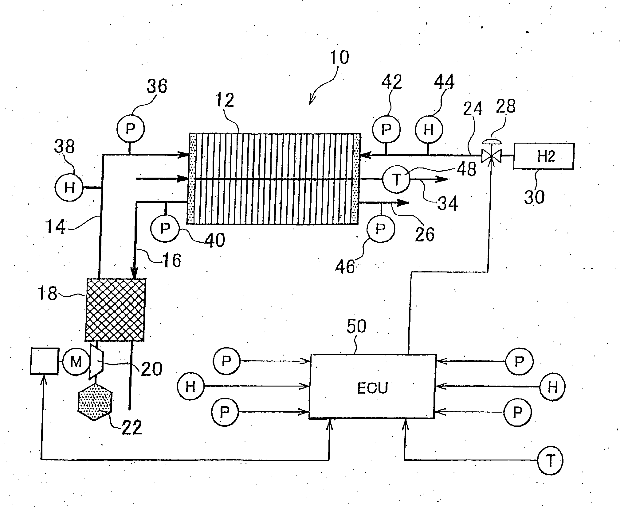
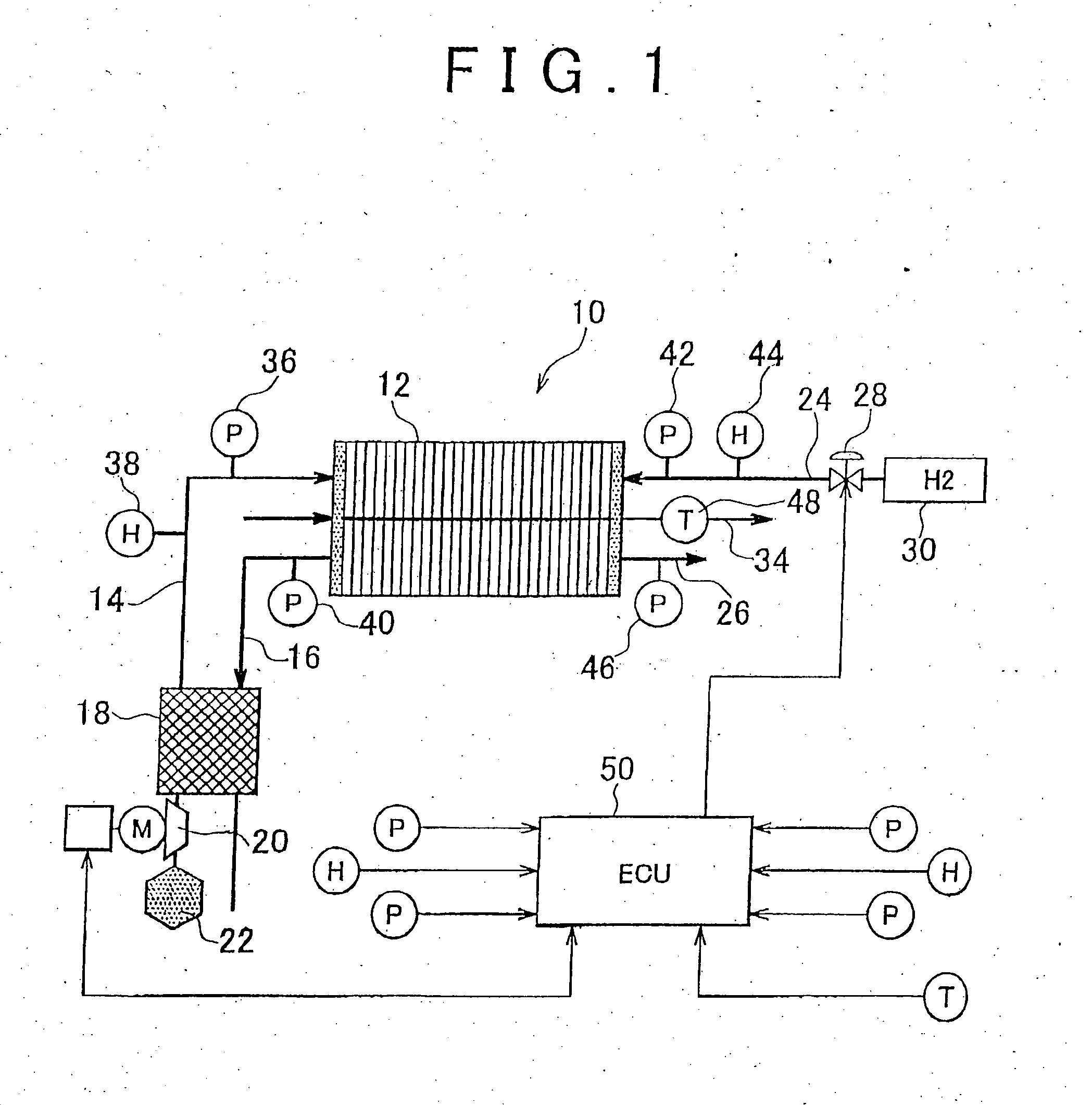
[0045]FIG. 1 is a diagram for explaining the configuration of a system according to the invention. The system shown in FIG. 1 is equipped with a fuel cell 10. The fuel cell 10 is equipped with a plurality of laminated membrane electrode assemblies 12. The membrane electrode assemblies 12 constitute a plate-like structure extending in the depth direction with respect to the sheet of FIG. 1.

[0046]An anode and a cathode are formed across an electrolyte membrane inside each of the membrane electrode assemblies 12. A gas flow channel for causing fuel gas containing hydrogen (hydrogen gas in this embodiment of the invention) to flow through the inside of a plane is formed on the anode side. A gas flow channel for causing oxidizing gas containing oxygen (air in this embodiment of the invention) to flow through the inside of a plane is formed on the cathode side. In addition, a coolant passage for causing coolant to flow therethrough is formed on a border between any adjacent ones of the me...

second embodiment

[0136]Next, the invention will be described with reference to FIGS. 9 to 12. The hardware configuration of this embodiment of the invention is identical to the configuration shown in FIG. 1 except in that the oxidizing gas flow channel and the fuel gas flow channel of each of the membrane electrode assemblies 12 form a counter flow channel. The system according to this embodiment of the invention is realized by causing the ECU 50 to execute a later-described routine shown in FIG. 11 in this hardware configuration.

[0137]As described above, in the system according to the first embodiment of the invention, the oxidizing gas flow channel and the fuel gas flow channel of each of the membrane electrode assemblies 12 form the coflow flow channel. That is, in the first embodiment of the invention, oxidizing gas on the cathode side and fuel gas on the anode side flow in the same direction. In this case, the power generation environment and the power generation state in the n−1 region decide ...


PUM


Abstract

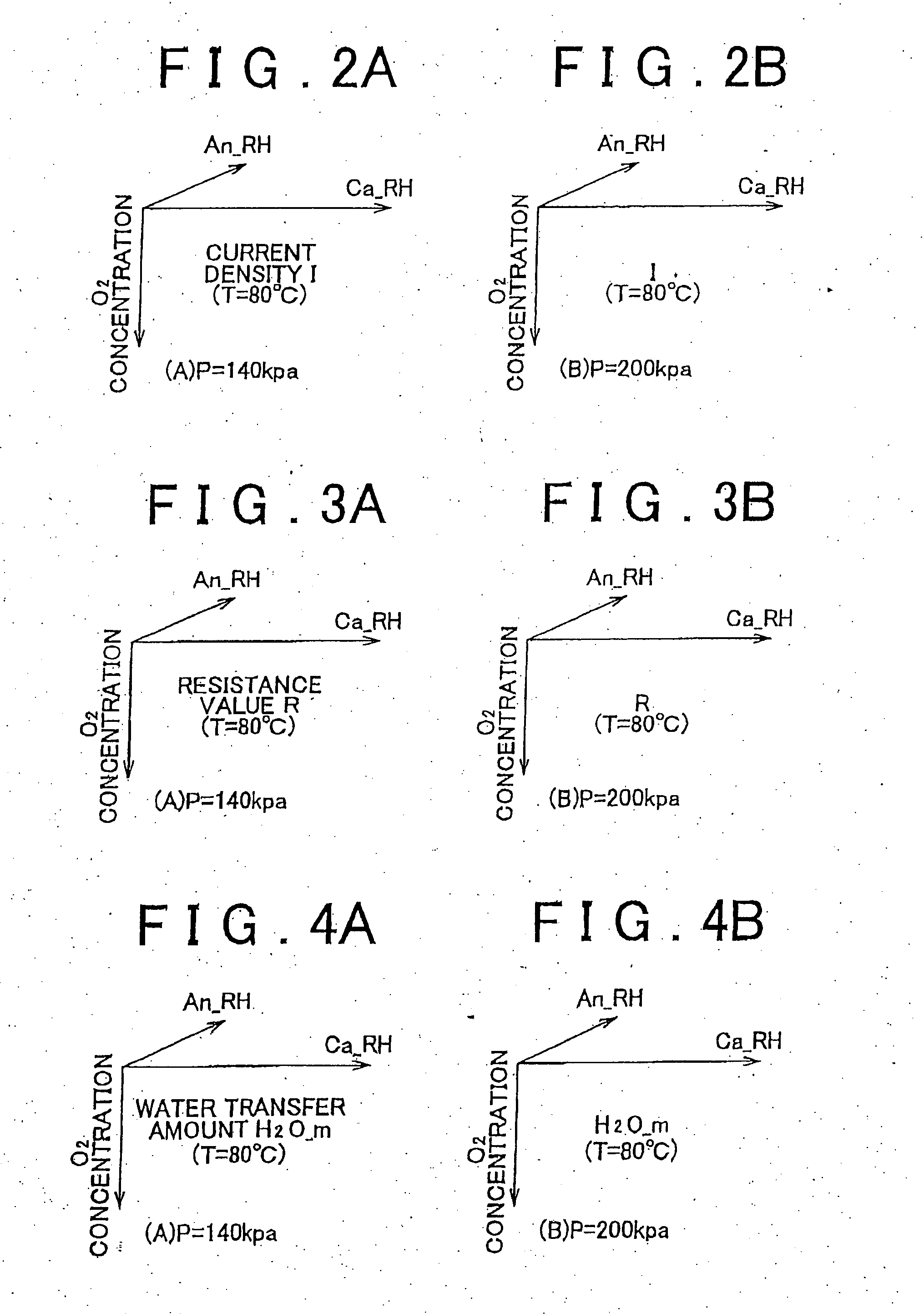
The membrane electrode assembly is virtually divided into a plurality of small regions arranged along the flow of reactive gases. A current density 132 and a transfer amount 136 of water in an n−1 region are calculated referring to the maps defining a relationship between a power generation environment and a current density and a relationship between the power generation environment and a transfer amount of water, on the basis of power generation environments 122 and 128 transmitted from a pre-stage. Consumption amounts 138 and 146 of the reactive gases are calculated from the current density 132. A power generation environment transmitted to an n region is calculated by reflecting the consumption amounts 138 and 146 of the reactive gases and the transfer amount 136 of water (140, 144, 148, 150). Power generation environments and power generation states are sequentially predicted as to all the small regions.

Description

BACKGROUND OF THE INVENTION[0001]1. Field of the Invention[0002]The invention relates to a fuel cell in-plane state estimating system and a fuel cell in-plane state estimating method, and more particularly, to an in-plane state estimating system and an in-plane state estimating method for accurately estimating a current distribution in a plane of each of membrane electrode assemblies constituting a fuel cell.[0003]2. Description of the Related Art[0004]Japanese Patent Application Publication No. 2005-347016 (JP-A-2005-347016) discloses a method for easily predicting an in-plane state of each of membrane electrode assemblies of a fuel cell. More specifically, the above-mentioned publication discloses a method in which a model of a membrane electrode assembly as an object to be predicted which is scaled down to 1 / n is created and used to predict an in-plane state of the membrane electrode assembly.[0005]In the aforementioned method of prediction, the in-plane state of the membrane ele...

Claims


Application Information

Patent Timeline
IPC IPC(8): H01M8/04
CPCH01M8/04089Y02E60/521H01M8/04365H01M8/04388H01M8/04395H01M8/04402H01M8/0441H01M8/045H01M8/04507H01M8/04582H01M8/04723H01M8/04753H01M8/04835H01M8/04992H01M8/1004H01M8/04119Y02E60/50
Inventor IKEDA, KOTARO
Owner TOYOTA JIDOSHA KK
Learn More