
Lubricant molded body, lubricant application apparatus, process cartridge, and image forming apparatus

a technology lubricant application, which is applied in the direction of mechanical equipment, instruments, distribution equipment, etc., can solve the problems of shortened exchange time of such parts, and increased cost of lubricant molded body. , to achieve the effect of reducing the cost of lubricant molded body, reducing the risk of cracking and cutting, and extending the use life of lubricant application

Inactive Publication Date: 2010-06-17
USAMI JOE
View PDF9 Cites 5 Cited by
  • Summary
  • Abstract
  • Description
  • Claims
  • Application Information

AI Technical Summary

Benefits of technology

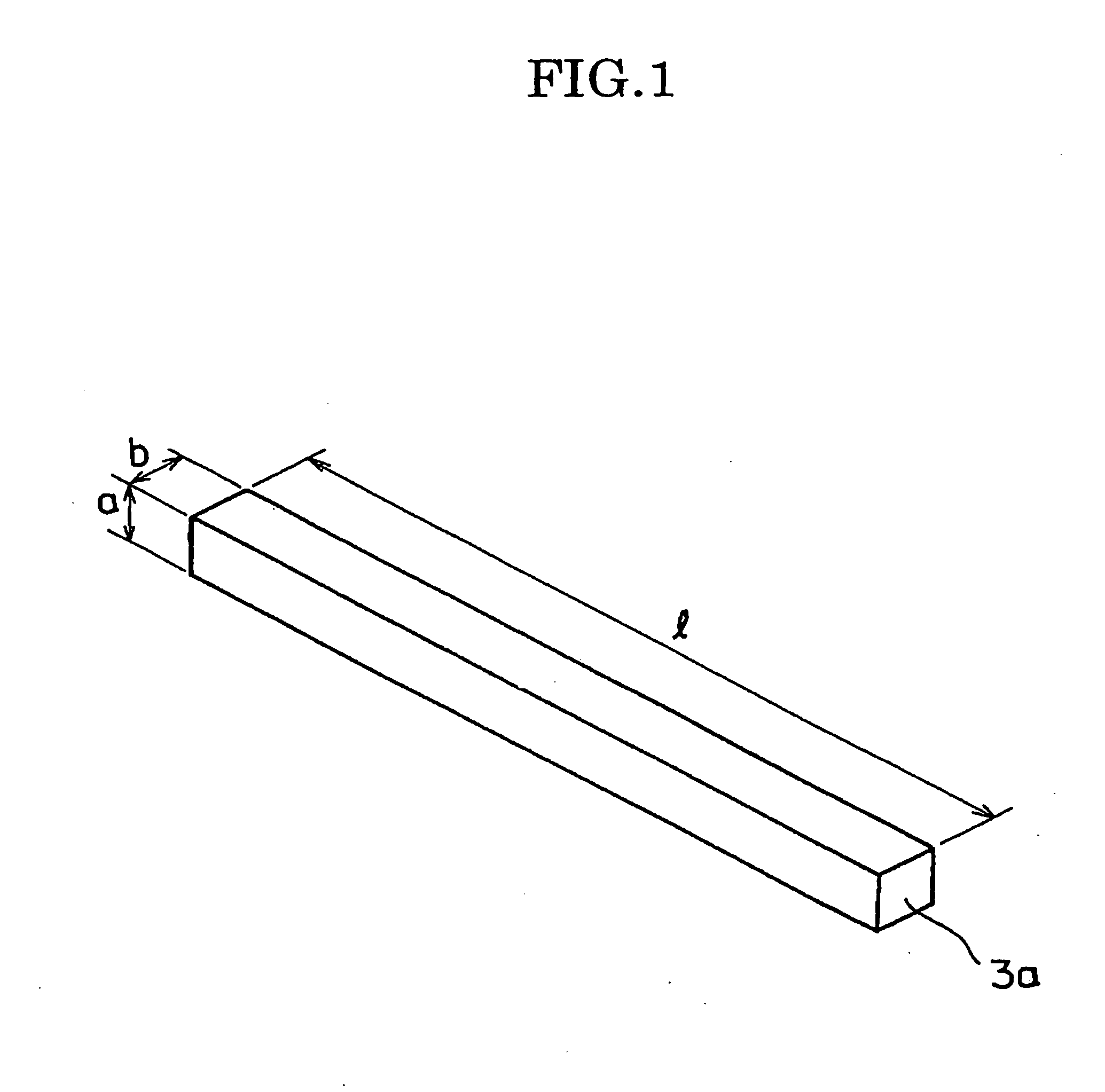
[0015]That is, a first object of the present invention is to provide a lubricant molded body, at a low cost, with a fewer cracking and cutting, regardless of the manufacturing method.
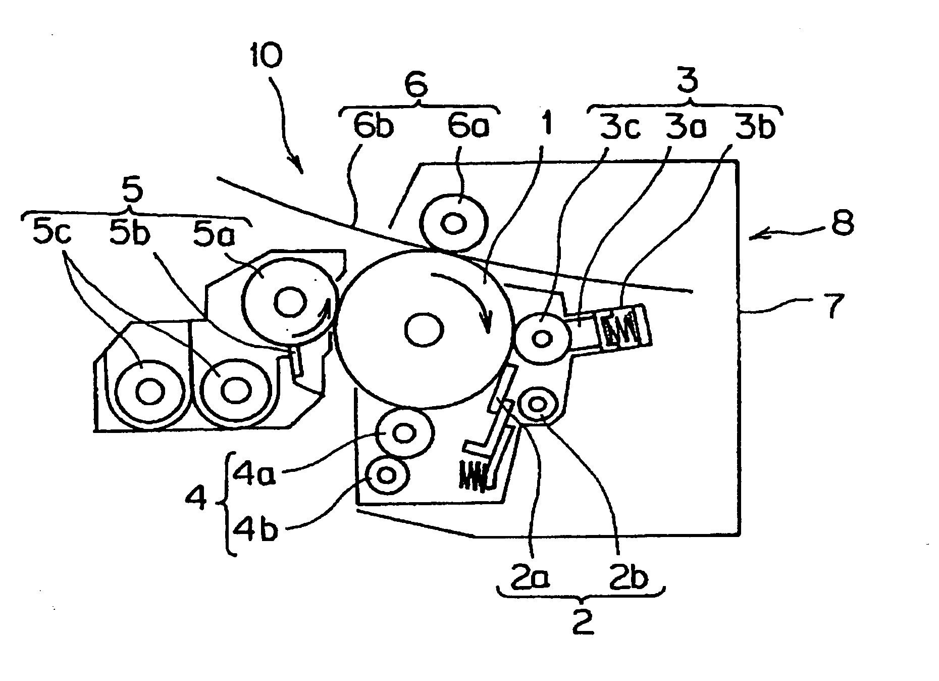
[0016]It is a second object of the present invention to provide a lubricant application apparatus, at a low cost, which applies a film of a lubricant of the lubricant molded body to a surface of an image carrier for electrophotograph. In a non-limiting embodiment, the lubricant may be adapted for use in an image forming apparatus, and the lubricant may include at least zinc stearate and zinc palmitate.
[0017]A third object of the present invention is to provide an image forming apparatus, at a low cost, which is equipped with the lubricant application apparatus.

Problems solved by technology

Furthermore, because the depth of wearing of the image carrier decreases, the use life of the image carrier becomes longer.
However, the shrinkage of the higher fatty acid metallic salt is large at the time of solidification in cooling.
Consequently, particularly when the higher fatty acid metallic salt was molded as a lubricant molded body having a rod-like shape with a large aspect ratio, there was a problem that the molded body was likely to be cracked or cut at the time of solidification in cooling.
Therefore, there was a problem that the initial investment cost increased.
However, there was also a problem in this technology that it was necessary to monitor the cooling temperature carefully.
Consequently, a uniformly cleaned state and a charging hazard are attained.

Method used


Image

  • Lubricant molded body, lubricant application apparatus, process cartridge, and image forming apparatus
  • Lubricant molded body, lubricant application apparatus, process cartridge, and image forming apparatus
  • Lubricant molded body, lubricant application apparatus, process cartridge, and image forming apparatus

Examples


example 1

[0073]Die portions 105 and 106 were assembled and fastened together via a middle die portion 104 as shown in FIG. 5 such that grooved faces of the die portions 105 and 106 contacted flat faces of the middle die portion 104, respectively. Each of the die portions 105 and 106 was made of a thick aluminum plate which had, at one face, nine grooves each having a width of 8 mm, a depth of 7 mm and a length of 380 mm. The thus assembled die was assembled and set to have totally eighteen channels, which could form totally eighteen blocks. A mixed solution was obtained by heating 99.9 wt % of zinc stearate and 0.1 wt % of silica (additive) up to 135° C., and was poured into the die heated to 150° C. with a heater, and then a heat insulating lid heated to 140° C. was placed on the die. After the die was kept at 150° C. for ten minutes, it was left in air to be cooled down to 105° C. Then, after the die was kept at 105° C. for fifteen minutes, it was left in air to be cooled down to 50° C. Fu...

example 2

[0076]Die portions 105 and 106 were assembled and fastened together via a middle die portion 104 as shown in FIG. 5 such that grooved faces of the die portions 105 and 106 contacted flat faces of the middle die portion 104, respectively. Each of the die portions 105 and 106 was made of a thick aluminum plate which had, at one face, nine grooves each having a width of 8 mm, a depth of 8 mm and a length of 390 mm. The die was assembled and set to have totally eighteen channels, which could form totally eighteen blocks. A mixed solution was obtained by heating 63 wt % of zinc stearate, 30 wt % of zinc palmitate, 3 wt % of zinc myristate, 2 wt % of zinc oleate, 1 wt % of zinc linoleate and 1 wt % of zinc arachidate up to 135° C. The resulting mixed solution was poured into the die heated to 150° C. with a heater, and then a heat insulating lid heated to 140° C. was placed on the die. After the die was kept at 160° C. for ten minutes, it was left in air to be cooled down to 105° C. Then,...

example 3

[0079]Die portions 105 and 106 are assembled and fastened together via a middle die portion 104 as shown in FIG. 5 such that grooved faces of the die portions 105 and 106 contacted flat faces of the middle die portion 104, respectively. Each of the die portions 105 and 106 was made of a thick aluminum plate which had, at one face, nine grooves each having a width of 11.5 mm, a depth of 16 mm and a length of 400 mm. The thus assembled die had totally eighteen channels, which could form totally eighteen blocks. A mixed solution was obtained by heating 99.5 wt % of zinc stearate and 0.5 wt % of magnesium stearate up to 140° C., and was poured into the die set and heated to 130° C. to 200° C. with a heater, and then a heat insulating lid heated to 140° C. was placed on the die. After the die was kept at 150° C. for ten minutes, it was left in air to be cooled down to not more than 40° C. Thereafter, the die was opened to obtain lubricant molded bodies made of zinc stearate. Such lubrica...


PUM

PropertyMeasurementUnit
average cell diameteraaaaaaaaaa
porosityaaaaaaaaaa
cell diametersaaaaaaaaaa

Abstract

A lubricant molded body, which is to be applied to a surface of a photosensitive layer for electrophotography in an image forming apparatus, for example, is composed of at least two kinds of higher fatty acid metallic salts having respectively different carbon numbers. As the higher fatty acid metallic salt that forms lubricant molded body, compounds such as zinc stearate, calcium stearate, barium stearate, aluminum stearate, zinc laurate, calcium laurate, etc. may be recited. The higher fatty acid metallic salts may contain at least one kind of fillers selected from the group consisting of silica, alumina, tungsten disulfide, molybdenum disulfide, graphite fluoride, graphite, boron nitride, polytetrafluoroethylene (PTFE), ethylene tetrafluoroethylene (ETFE), and polyvinylidene fluoride (PVDF).

Description

PRIORITY STATEMENT[0001]This application is a divisional claiming priority under 35 U.S.C. §121 to co-pending U.S. application Ser. No. 11 / 603,079, filed on Nov. 22, 2006, which claims priority under 35 U.S.C. §119 to Japanese Application No. 2005-342401, filed on Nov. 28, 2005, the entire contents of each of which are incorporated herein by reference.BACKGROUND[0002](1) Field[0003]The present invention relates to a lubricant molded body to be applied onto a surface of a photosensitive layer for electrophotograph, a lubricant application apparatus to apply the lubricant of the lubricant molded body to the surface of the photosensitive layer for the electrophotograph, a process cartridge equipped with the lubricant application apparatus, and an image forming apparatus equipped with the lubricant application apparatus.[0004](2) Description of the Related Art[0005]To improve the cleaning power of the electrophotography apparatus used with the copier or the like, a technique is proposed...

Claims


Application Information

Patent Timeline
Patent Type & Authority Applications(United States)
IPC IPC(8): G03G21/00C10M105/80F16N7/24
CPCC10M105/24C10M169/04C10N2270/00C10M169/041C10M2201/041C10M2201/042C10M2201/061C10M2201/062C10M2201/065C10M2201/066C10M2201/105C10M2207/126C10M2213/02C10M2213/06C10M2213/062C10N2210/01C10N2210/02C10N2210/07C10N2210/08C10N2240/06C10N2240/203C10N2250/08C10N2250/18C10N2010/14C10N2010/02C10N2010/04C10N2040/06C10N2040/175C10N2050/08C10N2050/14C10N2070/00C10N2010/16
Inventor USAMI, JOE
Owner USAMI JOE
Learn More