
Near-field light generating element comprising surface plasmon antenna with surface or edge opposed to waveguide

Active Publication Date: 2010-06-17
TDK CORPARATION
View PDF13 Cites 46 Cited by
  • Summary
  • Abstract
  • Description
  • Claims
  • Application Information

AI Technical Summary

Benefits of technology

[0009]Therefore, an object of the present invention is to provide a near-field light generating element in which reduced is the propagation loss of excited surface plasmon that propagates to the near-field light generating end, and the light use efficiency is improved.
[0017]In the above-described near-field light generating element, the propagation surface or the propagation edge of the surface plasmon antenna extends to the near-field light generating end, being opposed to a side surface of the waveguide. In this configuration, surface plasmon, which propagates on the propagation surface or the propagation edge and arrives at the near-field light generating end, can propagates without significantly changing its wavenumber during the propagation, which leads to a less propagation loss, and to an improved light use efficiency.
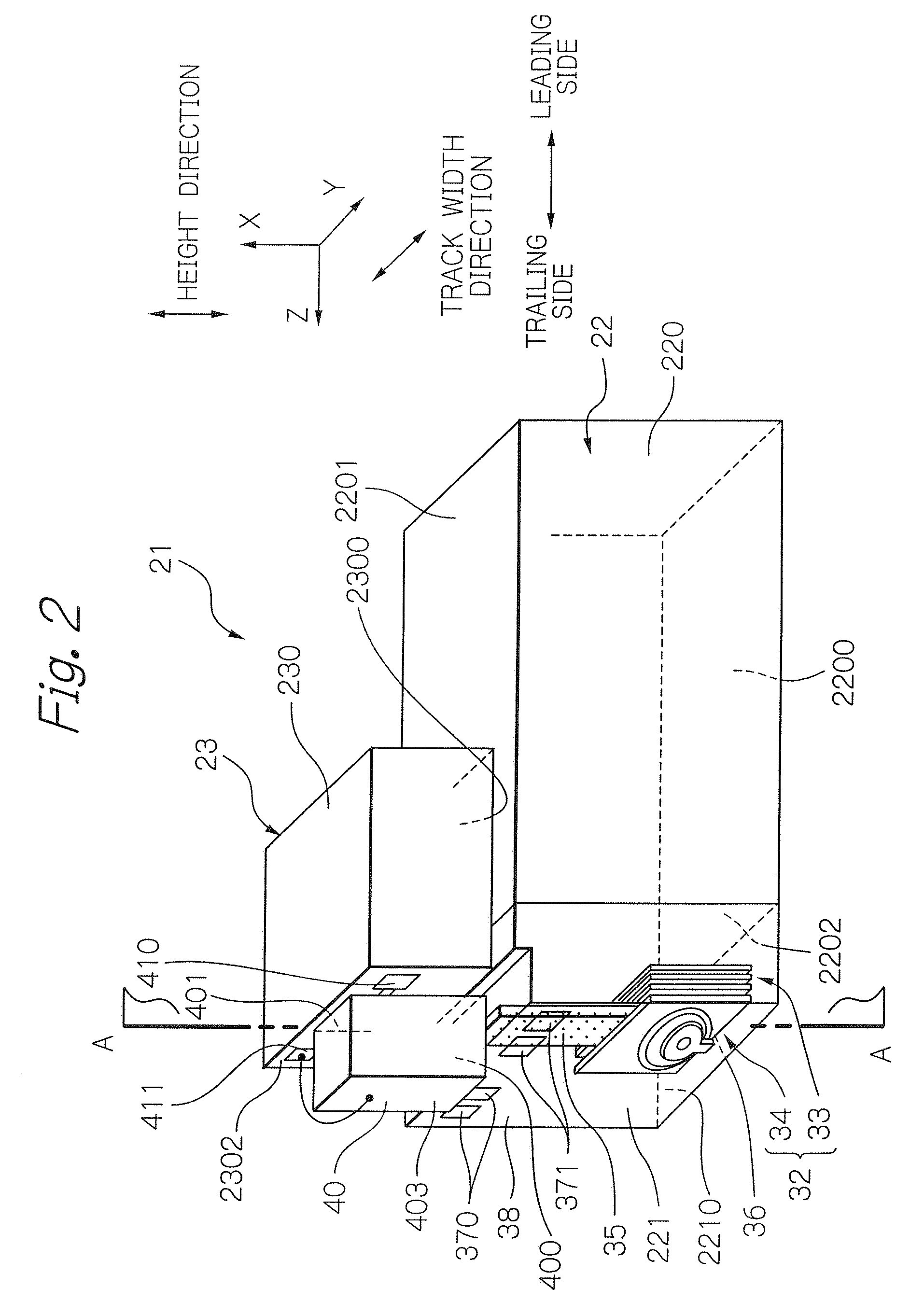
[0025]In the thermally-assisted magnetic recording head according to the present invention, the waveguide is preferably provided in a side opposite to the magnetic pole in relation to the plasmon antenna. Further, a portion on the opposed-to-medium surface side of the plasmon antenna is preferably inclined so as to become closer to an end portion on the opposed-to-medium surface side of the magnetic pole toward the opposed-to-medium surface. Furthermore, a portion on the opposed-to-medium surface side of the magnetic pole is preferably inclined so as to become closer to an end portion on the opposed-to-medium surface side of the plasmon antenna toward the opposed-to-medium surface. With these configurations, the waveguide can be sufficiently separated apart from the magnetic pole, while the near-field light generating end of the plasmon antenna is set to a position adjacent to the end surface on the opposed-to-medium surface side of the magnetic pole. Resultantly, there can be avoided such a situation in which a part of the light is absorbed into the magnetic pole, and the amount of light to be converted into near-field light is reduced. Further, it is preferable that a thermal conduction layer is provided between the plasmon antenna and the magnetic pole, so as to cover an end surface of the plasmon antenna, the surface being opposite to the propagation surface or the propagation edge.

Problems solved by technology

However, the decrease in size of the magnetic microparticles raises a problem of degradation in thermal stability of the magnetization due to the decrease in volume.

Method used


Image

  • Near-field light generating element comprising surface plasmon antenna with surface or edge opposed to waveguide
  • Near-field light generating element comprising surface plasmon antenna with surface or edge opposed to waveguide
  • Near-field light generating element comprising surface plasmon antenna with surface or edge opposed to waveguide

Examples


Embodiment Construction

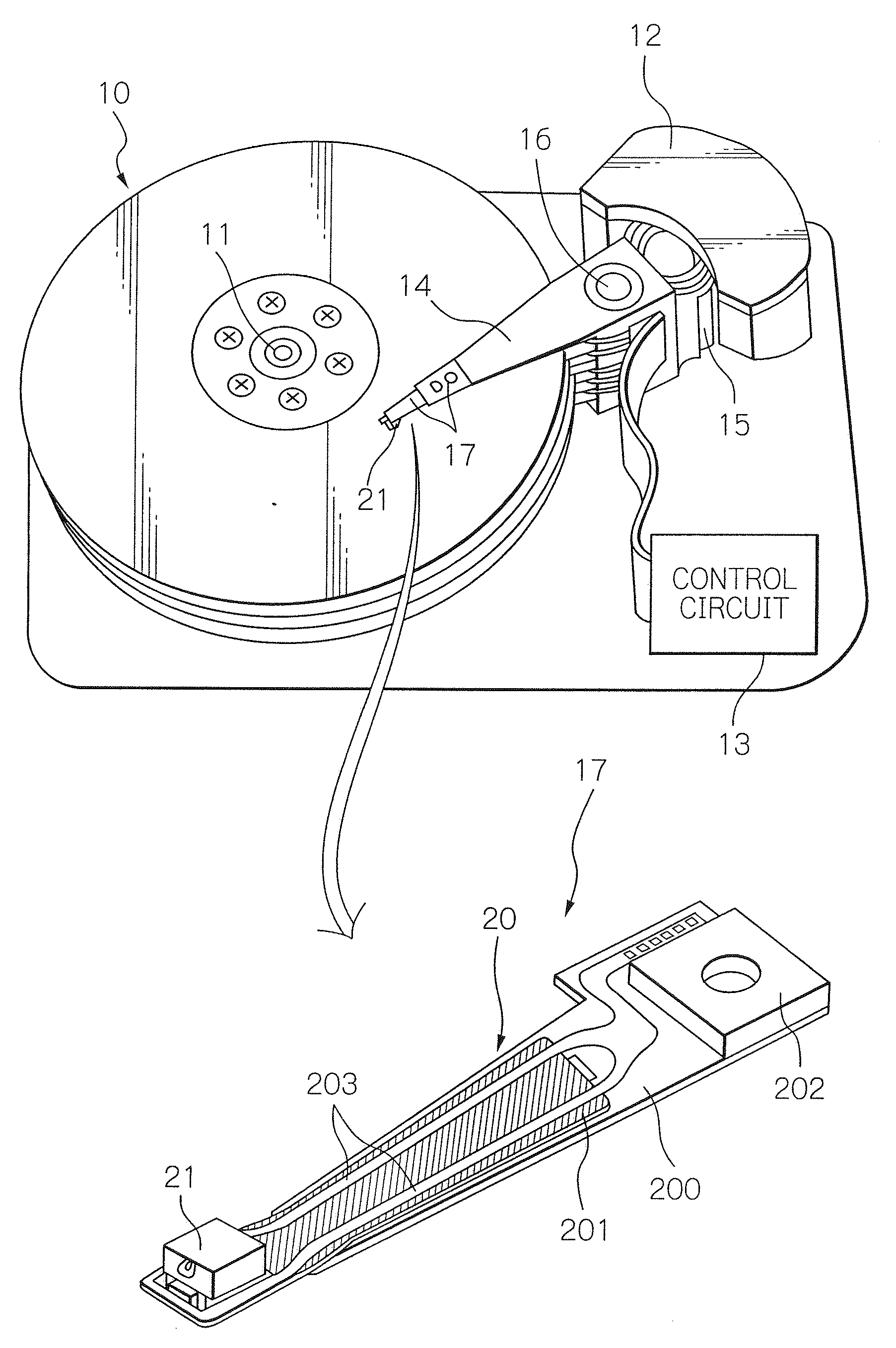
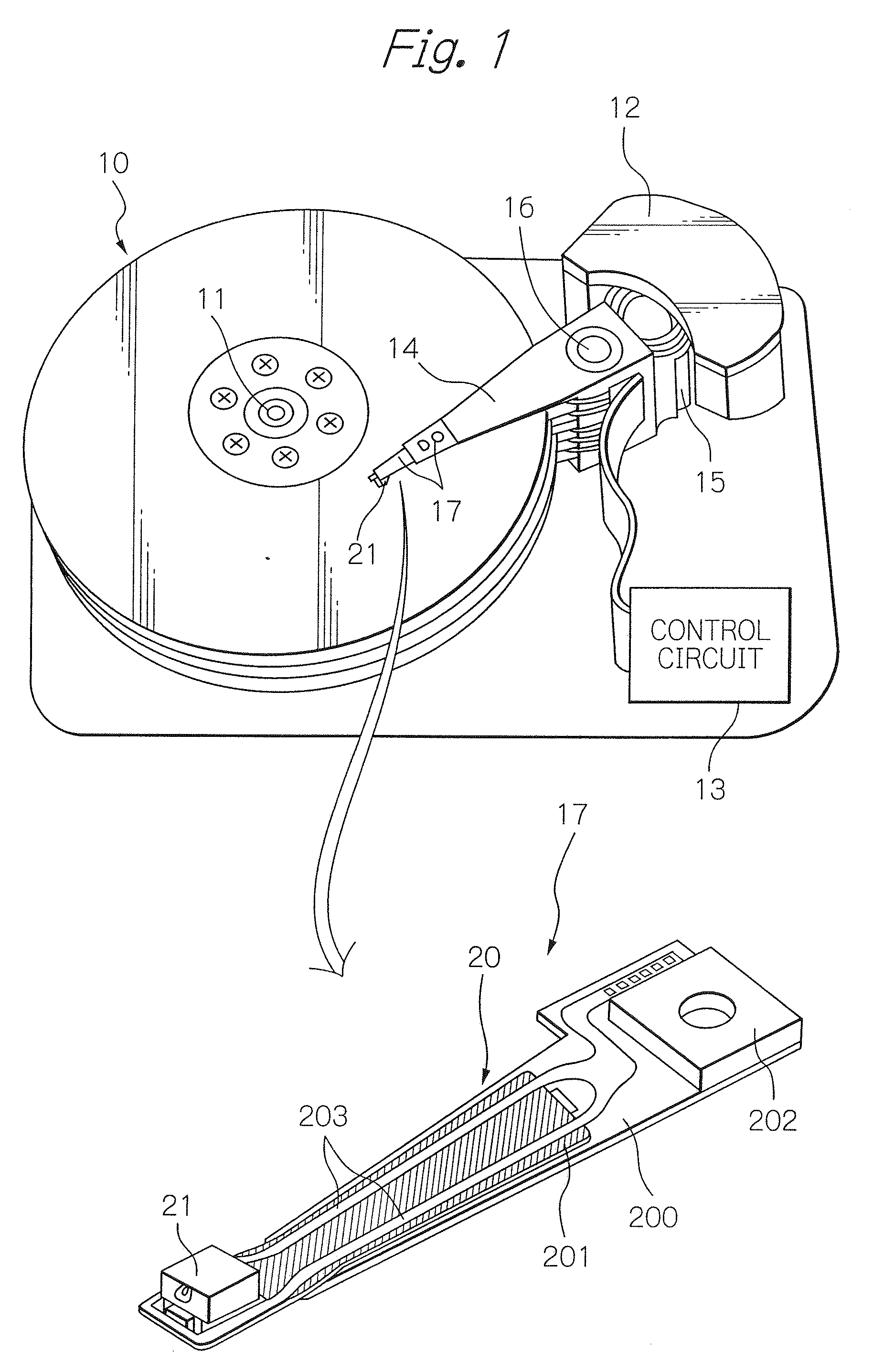
[0039]FIG. 1 shows a perspective view schematically illustrating a structure of a major part in one embodiment of a magnetic recording apparatus and an HGA according to the present invention. Here, in the perspective view of the HGA, the side of the HGA, opposed to the surface of the magnetic recording medium, is presented as the upper side.

[0040]A magnetic disk apparatus as a magnetic recording apparatus shown in FIG. 1 includes: a plurality of magnetic disks 10 as magnetic recording media, rotating around a rotational axis of a spindle motor 11; an assembly carriage device 12 provided with a plurality of drive arms 14 thereon; a head gimbal assembly (HGA) 17 attached on the top end portion of each drive arm 14 and provided with a thermally-assisted magnetic recording head 21 as a thin-film magnetic head; and a recording / reproducing and light-emission control circuit 13 for controlling write / read operations of the thermally-assisted magnetic recording head 21 and further for contro...


PUM


Abstract

Provided is a near-field light generating element in which reduced is the propagation loss of excited surface plasmon that propagates to the near-field light generating end. The element comprises: a waveguide through which light for exciting surface plasmon propagates; and a plasmon antenna comprising a near-field light generating end and a propagation surface or edge. The propagation surface or edge extends to the near-field light generating end, and causes surface plasmon excited by the light to propagate thereon. Further, a portion of the side surface on the near-field light generating end side is opposed to the propagation surface or edge with a predetermined distance so as for the light to be coupled with the plasmon antenna in a surface plasmon mode. In this configuration, surface plasmon can propagates without significantly changing its wavenumber, which leads to a less propagation loss, and to an improved light use efficiency.

Description

BACKGROUND OF THE INVENTION[0001]1. Field of the Invention[0002]The present invention relates to a plasmon antenna for generating near-field light by being irradiated with light. And the present invention relates to a head used for thermally-assisted magnetic recording in which a magnetic recording medium is irradiated with near-field light, thereby anisotropic magnetic field of the medium is lowered, thus data can be written. Further, the present invention relates to a magnetic recording apparatus provided with the head.[0003]2. Description of the Related Art[0004]As the recording density of a magnetic disk apparatus becomes higher, further improvement has been required in the performance of a thin-film magnetic head and a magnetic recording medium. As the thin-film magnetic head, a composite-type thin-film magnetic head is widely used, which has a stacked structure of a magnetoresistive (MR) element for reading data and an electromagnetic transducer for writing data.[0005]Whereas,...

Claims


Application Information

Patent Timeline
IPC IPC(8): G11B11/00G11B5/02
CPCG11B5/314G11B5/4866G11B2005/0021G11B7/1387G11B2005/001G11B5/6088
Inventor KOMURA, EIJISHIMAZAWA, KOJIMIYAUCHI, DAISUKE
Owner TDK CORPARATION
Learn More