Voltage buck-boost switching regulator
a switching regulator and voltage buck technology, applied in the field of switching regulators, can solve the problems of increasing the order of frequency transfer functions, increasing the cost, and affecting the operation, and achieve the effect of stable, high-speed, high-efficiency constant-voltage output operation
- Summary
- Abstract
- Description
- Claims
- Application Information
AI Technical Summary
Benefits of technology
Problems solved by technology
Method used
Image
Examples
Embodiment Construction
[0049]The voltage buck-boost switching regulator of the present invention with said constitution and operation makes it possible to output a stable, high-speed, high-efficiency constant voltage without a complicated, large-scale, and high-cost phase compensation circuit.
[0050]In the following, an explanation will be given regarding preferred embodiments of the present invention with reference to FIGS. 1-13.
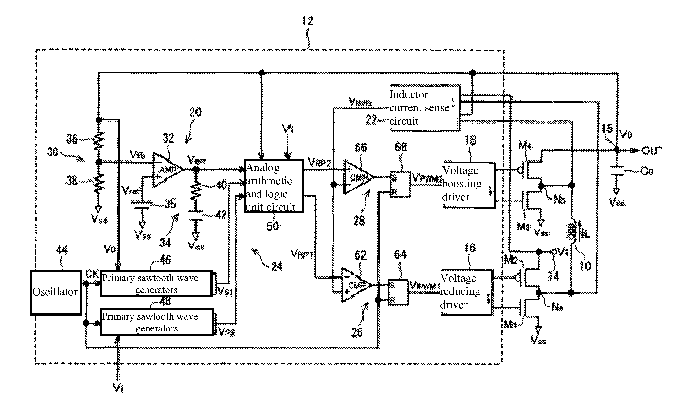
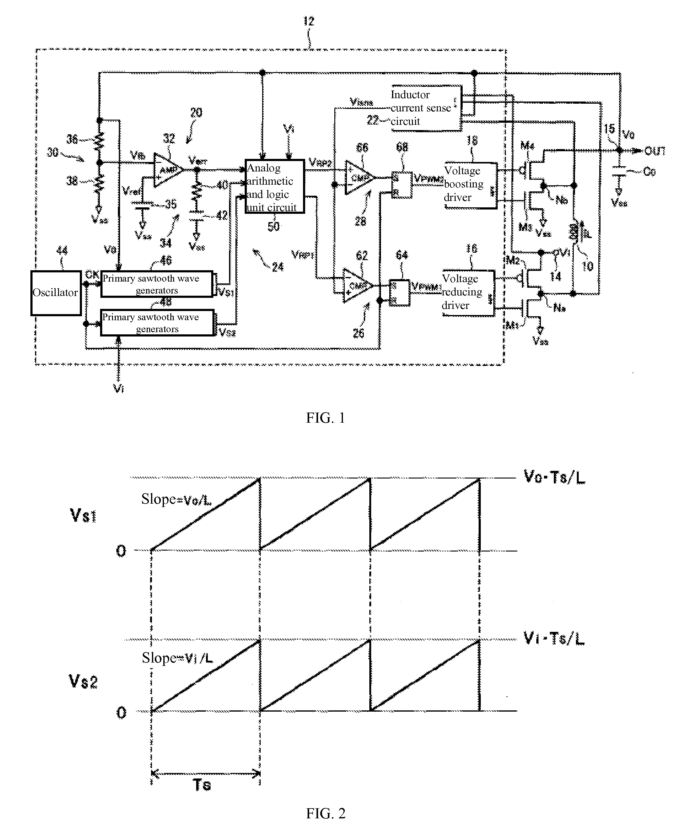
[0051]FIG. 1 is a diagram illustrating the constitution of the circuit of the voltage buck-boost switching regulator in an embodiment of the present invention.
[0052]This voltage buck-boost switching regulator has a pair of voltage reducing transistors M1, M2, a pair of voltage boosting transistors M3, M4, inductance coil 10, output capacitor Co and controller 12.
[0053]More specifically, the two terminals of inductance coil 10 are connected to nodes Na, Nb, respectively. Then, NMOS transistor M1 is connected between reference voltage terminal (Vss) at ground potential and node Na, ...
PUM
 Abstract
Description
Claims
Application Information
 - R&D
- Intellectual Property
- Life Sciences
- Materials
- Tech Scout
- Unparalleled Data Quality
- Higher Quality Content
- 60% Fewer Hallucinations
Browse by: Latest US Patents, China's latest patents, Technical Efficacy Thesaurus, Application Domain, Technology Topic, Popular Technical Reports.
© 2025 PatSnap. All rights reserved.Legal|Privacy policy|Modern Slavery Act Transparency Statement|Sitemap|About US| Contact US: help@patsnap.com


