
Container with Flattened Cap

a container and flattened technology, applied in the field of containers, can solve the problems of significant cost, indistinguishable pla and similar plastics from normal plastics, and slow decomposition rate, and achieve the effect of preventing tampering

Active Publication Date: 2010-06-17
THE WEST CO INC
View PDF23 Cites 15 Cited by
  • Summary
  • Abstract
  • Description
  • Claims
  • Application Information

AI Technical Summary

Benefits of technology

[0019]In preferred embodiments, the non-rigid tube body and the cap form a cylindrical shape having tapered sealed ends. It is also contemplated that the walls of the body and the cap could be shaped to have polygonal, oval or other horizontal cross-sectional shapes. In addition, the walls could even form a cone, or be frustoconical shaped. The wall of the body of the tube and cap could be any thickness, but is preferably no more than 0.5 mm thick. As used herein the term “tube” means any compressible or non-compressible container used for housing objects, solids, liquids, and semi-solids. As used herein a “narrow tube” is one in which the length of the tube is at least 3 / π times the cross-sectional area of the open end of the body taken perpendicular to a long axis of the tube. The walls of the tube / cap typically include 1 to 5 layers (e.g. wraps), and most preferably 3 layers of the paper / coating combination. As used herein, the term “non-rigid” with respect to the body means that a user can realistically use his / her fingers to compress some portion of the walls of the body sufficiently to dispense the semi-solid.
[0023]In preferred embodiments, the open end of the cap is sized and dimensioned to slidably engage an exterior surface of the open end of the tubular body. Preferred caps have a longitudinal dimension that is less than a longitudinal dimension of the tube body; however it is contemplated that the cap could have a longitudinal dimension greater than the tube body—to accommodate the tube body being nested within the cap. In still other embodiments the cap can comprise an interior flat surface that pushes the semi-solid composition back into the tube body when the cap mates with the body, and also a sliding tapered insert could be disposed within the lumen of the tube body to aid in the dispensing of the semi-solid composition. It is also contemplated that a safety opening strip could securely hold the tube body and the cap together to prevent tampering.

Problems solved by technology

Much of the waste comes from plastic and / or metal, both of which decompose at a very slow rate.
Unfortunately, plastic dispensing containers are used in almost every consumer market.
However, such plastics still require specialized processes and facilities for degradation, which results in significant costs.
In addition, PLA and similar plastics are visibly indistinguishable from normal plastics.
This can be problematic because if the PLA is inadvertently placed within a group of traditional plastics to be recycled, the PLA can interfere with the entire recycling process.
Unfortunately, Hill contemplates an inner plastic protective layer for presumably rendering the container impermeable to its contents.
The use of foils and polymers in Lowry impart biodegradability issues and still contribute to our landfill problems.
Tojo makes a significant improvement over the previous paper containers by molding pulp fibers; but like Hill and Lowry, Tojo's synthetic resin imparts biodegradability issues.
Still further, Tojo contemplates that a molded cap can be used with the container, but Tojo fails to contemplate the cap being coated.
However, Sullivan fails to contemplate coating other areas of the inner sleeve, or the cap portion of the outer sleeve.
Thus, like Tojo, Sullivan fails to contemplate a paper container having a coated cap.

Method used


Image

  • Container with Flattened Cap
  • Container with Flattened Cap
  • Container with Flattened Cap

Examples


Embodiment Construction

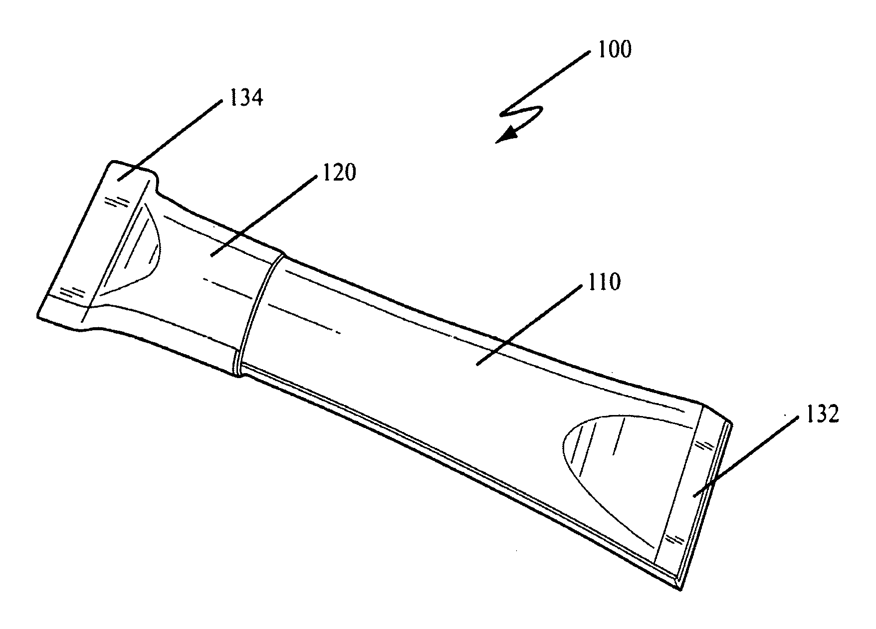
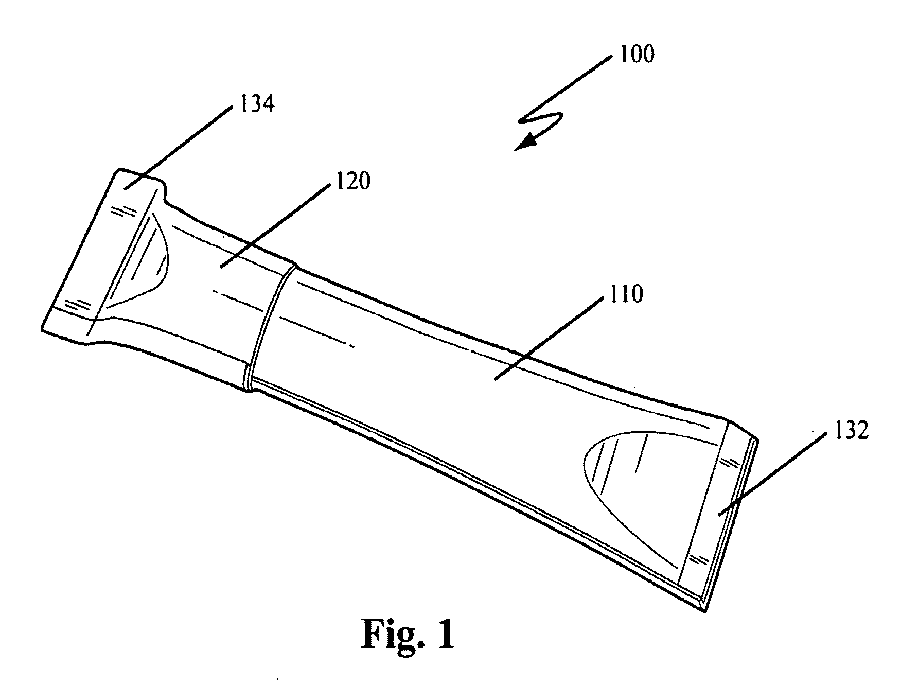
[0039]FIG. 1 generally depicts tube 100 of the present invention, comprising a tubular body 110 and a tubular cap 120 mated with body 110. As shown in FIG. 1, body 110 and cap 120 have tapered sealed ends 132 and 134, respectively.

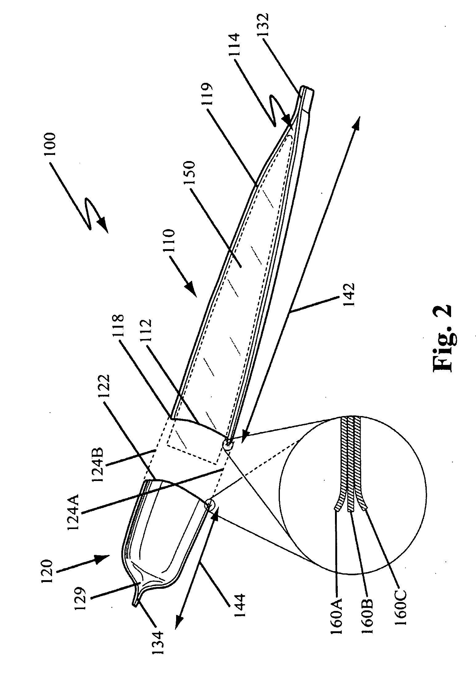
[0040]FIG. 2 is a cross sectional view of tube 100 of FIG. 1 having tubular body 110 and cap 120. As shown in FIG. 2, body 110 has an open end 112, a tapered sealed end 132, and a lumen 114 defined by the walls of body 110 containing a semi-solid composition 150. Cap 120 is depicted as having an open end 122 and a tapered sealed end 134, and a lumen defined by the walls of the cap 120. The open end 122 of cap 120 is sized and dimensioned to slidably engage an exterior surface 118 of the open end 112 of the body 110 (shown by dotted lines 124A and 124B). It is contemplated that an interior surface 119 of body 110 and an interior surface 129 of cap 120 have a substantially impermeable coating (not shown) to the semi-solid composition 150.

[0041]In a preferred...


PUM

PropertyMeasurementUnit
thicknessaaaaaaaaaa
thickaaaaaaaaaa
diametersaaaaaaaaaa

Abstract

A biodegradable tube comprises a mom-rigid paper tubular body defining a lumen for containing a semi-solid composition; a paper tubular cap that slidably mates with the body; and wherein interior surfaces of the each of the body and the cap have a coating that is substantially impermeable to the semi-solid composition. In preferred embodiments the tube body and cap have tapered sealed ends, the coating comprises an adhesive, and the walls of the tube / cap comprise a rolled paper material upon which the coating has been applied. Contemplated semi-solid product materials include for example lip balm, facial cream, lotion, deodorant, sunscreen, caulk, grease sticks, mosquito repellant, and shoe polish.

Description

RELATED APPLICATIONS[0001]This application claims priority and herein incorporates by reference U.S. provisional patent application Ser. No. 61 / 193689, filed Dec. 16, 2008.FIELD OF THE INVENTION[0002]The field of the invention is containers, and more specifically biodegradable containers for dispensing a semi-solid composition.BACKGROUND[0003]Americans currently produce more waste than any other nation in the world. Much of the waste comes from plastic and / or metal, both of which decompose at a very slow rate. These materials must be recycled, dumped into the oceans or waterways, or deposited into landfills where they will remain for centuries. Unfortunately, plastic dispensing containers are used in almost every consumer market.[0004]In order to reduce the waste in our ever-filling landfills, it is advantageous to create containers that are biodegradable and / or compostable. In an attempt to provide a more degradable container, the use of plastics such as polylactic acid polymers (P...

Claims


Application Information

Patent Timeline
Patent Type & Authority Applications(United States)
IPC IPC(8): B65D69/00B65D35/00
CPCB65D35/14B65D35/44B65D65/466Y10S206/822B65D2101/0023B65D2203/00Y10S206/823B65D2101/0007B65D2401/05B65D2401/15Y02A40/90Y02W90/10
Inventor WEST
Owner THE WEST CO INC
Learn More