
Lamp socket

Inactive Publication Date: 2010-06-10
DONETSKY YURIJ
View PDF4 Cites 0 Cited by
  • Summary
  • Abstract
  • Description
  • Claims
  • Application Information

AI Technical Summary

Benefits of technology

[0005]The present invention provides a combination of the following technological effects: simplified design and reduced risk of injury when replacing even a hot electric bulb.

Problems solved by technology

It also takes an effort to remove a faulty (burned-out) electric bulb.
Due to the widespread use of lighting devices, the labor-intensive process of installing and replacing electric bulbs causes substantial financial losses.
It is especially difficult to remove an electric bulb with a broken bulb glass, since it is difficult to apply the required force without holding the bulb.
A risk of injury is involved.
In case of non-elastic deformation of contacts due to mechanical or thermal impacts, the risk of a lighting device malfunction increases.
This raises the risk of electrocution.
Yet, the design described here is rather complex compared to a standard lamp socket.
The arm releasing the electric bulb base from the clamp is located close to the electric bulb, so there is a risk of sustaining burns if the electric bulb is still hot.

Method used


Image

  • Lamp socket
  • Lamp socket
  • Lamp socket

Examples


Embodiment Construction

[0011]While the invention may be susceptible to embodiment in different forms, there are shown in the drawings, and will be described in detail herein, specific embodiments of the present invention, with the understanding that the present disclosure is to be considered an exemplification of the principles of the invention, and is not intended to limit the invention to that as illustrated and described herein.

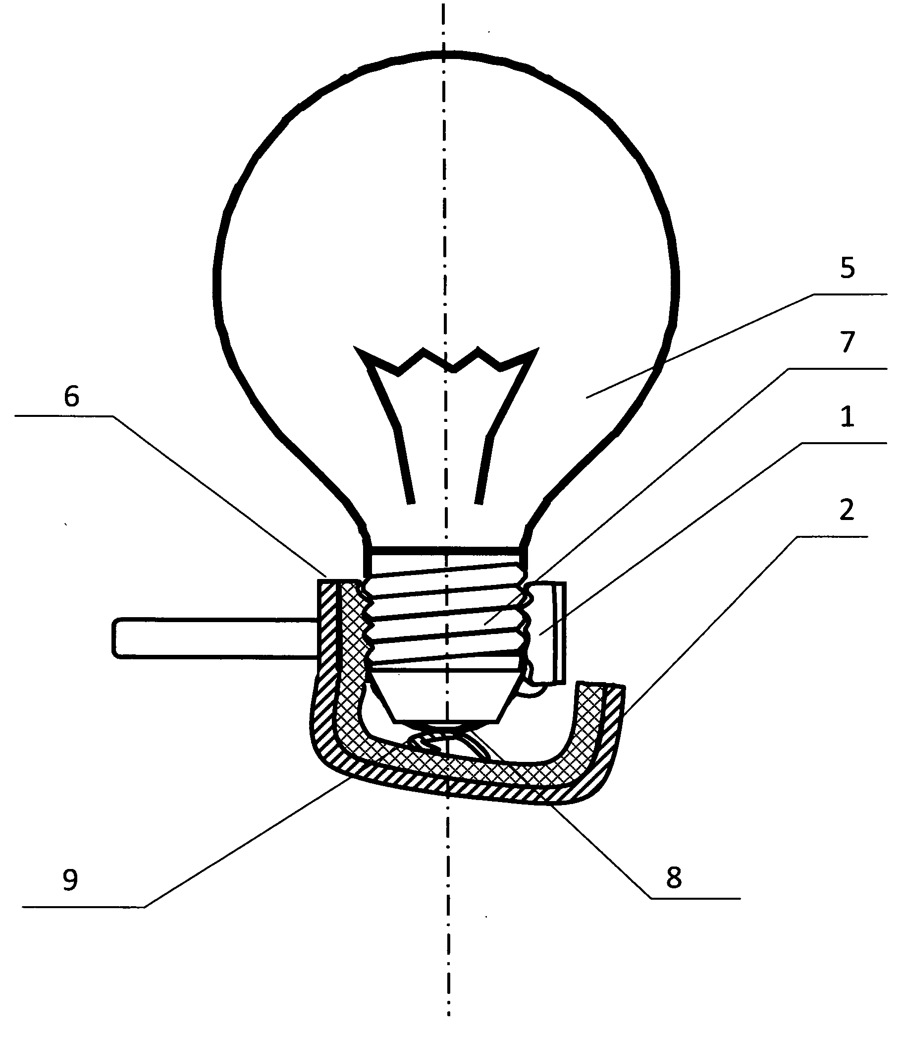
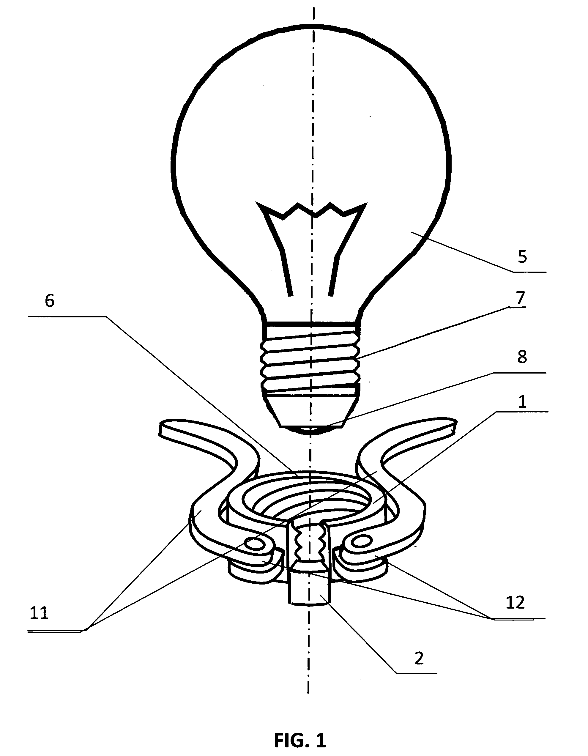
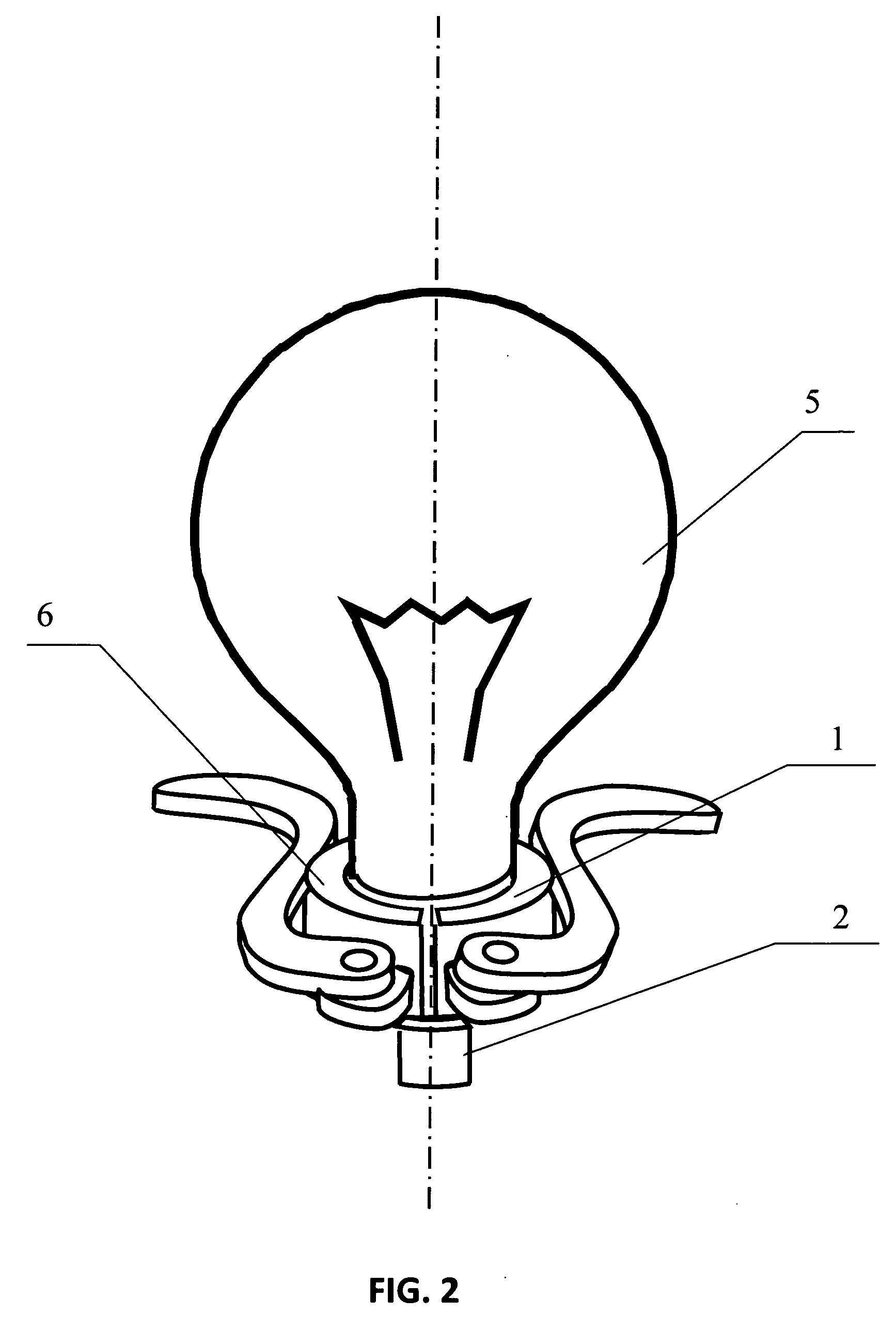
[0012]A preferred embodiment of the inventive lamp socket (6) (illustrated on FIGS. 1-4) comprises: a clamp (shown on FIG. 1), including an embracing section (1) and a retainer (2), which retainer constitutes a single whole with the embracing section (1) and made of a dielectric material (3) loaded with a reinforcing spring (4) (shown on FIG. 3). The lamp socket (6) comprises a contact (9) located on the retainer (2), and a contact (10) (FIG. 3) located on the embracing section (1). The lamp socket (6) comprises a clamp opening clasp (12), including arms (11) (shown on FIG. 1). ...


PUM


Abstract

A lamp socket is disclosed for connecting an electric bulb, having a base, base contact, and bottom contact, to an electrical grid. The socket comprises (a)—a clamp including a spring-loaded embracing section with a first contact, capable of passing the base through in an open position and gripping it in a closed position, and—a spring-loaded dielectric retainer, having a second contact, capable of retaining the section in the open position and releasing it into the closed position upon being depressed by the base, and (b) a spring-loaded clasp, capable of expanding the section in to the open position. While the clamp is being in the closed position, the first contact is depressed by the base contact, and the second contact is depressed by the bottom contact. The section and retainer can be made as a single whole, and spring-loaded by one spring. The socket increases safety of operation.

Description

CROSS-REFERENCES TO RELATED APPLICATIONS[0001]This application is a U.S. national phase application of a PCT application PCT / RU2008 / 000353 filed on 6 Jun. 2008, published as WO2009025579, whose disclosure is incorporated herein in its entirety by reference, which PCT application claims priority of a Russian Federation patent application RU2007131371 filed on 17 Aug. 2007.FIELD OF THE INVENTION[0002]This invention belongs to the field of electrical engineering. It can be used in electrical lighting devices to connect electric bulbs.BACKGROUND OF THE INVENTION[0003]A conventional lamp socket typically consists of a case, an electric bulb cap, and spring-loaded electric contacts. The electric bulb cap is a cylindrical sleeve. The sleeve has a helical groove or a bayonet retainer. The electric bulb is installed into the lamp socket with a helical groove or a bayonet retainer with an application of effort. The effort ensures the spring-loaded contacts of the lamp socket press against the...

Claims


Application Information

Patent Timeline
IPC IPC(8): H01R24/00
CPCH01R4/48H01R33/22H01R13/193
Inventor DONETSKY, YURIJ
Owner DONETSKY YURIJ
Learn More