
Back support structure

a back support and back support technology, applied in the field of back support structures, can solve the problems of user discomfort, user back muscles and/or spine strain, and even more severe problems for users suffering from back related problems

Inactive Publication Date: 2010-06-10
EVERETT MELVIN
View PDF6 Cites 3 Cited by
  • Summary
  • Abstract
  • Description
  • Claims
  • Application Information

AI Technical Summary

Benefits of technology

[0008]Accordingly, an object of the present disclosure is to provide an adjustment of a cushioning effect of a backrest support according to a user's requirement for supporting his / her back in a convenient manner.
[0009]Another object of the present disclosure is to provide such a surface of a backrest support on which a user may support his / her back comfortably in order to reduce strain on his / her back muscles and / or spine.
[0010]In view of the foregoing disadvantages inherent in the prior art, the general purpose of the present disclosure is to provide a support structure for supporting a user's back, configured to include all the advantages of the prior art, and to overcome the drawbacks inherent therein.
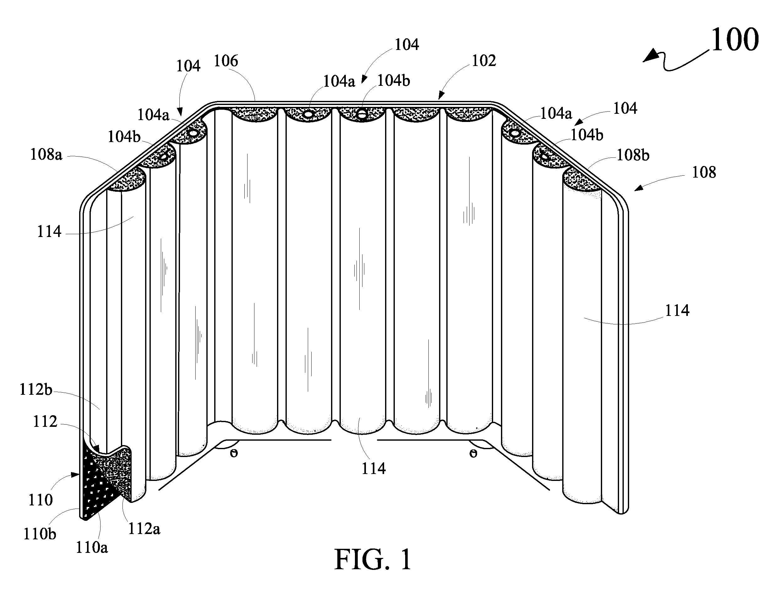
[0011]The support structure includes a body member and at least one air interface. The body member includes a plurality of members, such as a middle support member and a pair of side support members. The pair of side support members is configured with the middle support member such that the middle support member is disposed between a first side support member and a second side support member of the pair of side support members. The first side support member and the second side support member are configured with the middle support member at a pre-determined angle with respect to the middle support member. The plurality of members includes a base layer and a cushion layer disposed on the base layer. The cushion layer is configured to be inflated with air to support the user's back. The at least one air interface is disposed on each member of the plurality of members. The at least one air interface is configured to inflate air into the cushion layer, and is configured to deflate air from the cushion layer of the each member of the plurality of members. Such inflation and deflation enable a selection of a desired amount of air into the cushion layer of the each member of the plurality of members for supporting the user's back.
[0013]Moreover, a support structure package is provided. The support structure package includes a support structure and a covering member. The support structure configured to support a user's back. The support structure includes a body member and at least one air interface. The body member includes a plurality of members, such as a middle support member and a pair of side support members. The pair of side support members is configured with the middle support member such that the middle support member is disposed between a first side support member and a second side support member of the pair of side support members. The first side support member and the second side support member are configured with the middle support member at a pre-determined angle with respect to the middle support member. The plurality of members includes a base layer and a cushion layer disposed on the base layer. The cushion layer is configured to be inflated with air to support the user's back. The at least one air interface is disposed on each member of the plurality of members. The at least one air interface is configured to inflate air into the cushion layer, and is configured to deflate air from the cushion layer of the each member of the plurality of members. Such inflation and deflation enable a selection of a desired amount of air into the cushion layer of the each member of the plurality of members for supporting the user's back. Further, the covering member includes an inner surface and an outer surface. The inner surface configures a cavity portion for receiving the support structure, and the outer surface is capable of protecting the support structure upon the support structure being received in the cavity portion.
[0014]The support structure includes the at least one air interface disposed on the each member of the plurality of members. The at least one air interface is configured to inflate air into the cushion layer, and is configured to deflate air from the cushion layer of the each member of the plurality of members, thereby enabling the user to adjust the cushioning effect of the support structure according to his / her requirement for supporting his / her back in a convenient manner. Further, the cushion layer includes such a surface on which the user may support his / her back comfortably in order to reduce strain on his / her back muscles and / or spine. More particularly, the cushion layer includes the plurality of protruding members disposed on the front surface of the cushion layer. The plurality of protruding members is configured to support the user's back comfortably in order to reduce strain on his / her back muscles and / or spine.

Problems solved by technology

Generally, the user may need to sit on such seat for long hours while working in the office or driving vehicles.
Sitting on such seat for long hours causes discomfort to the user.
Particularly, back muscles and / or spine of the user may get strained if there is lack of proper support to the user's back.
This problem is even more severe for users suffering from back related problems.
However, such additional backrest support has various drawbacks associated therewith.
Adding and removing the cushioning material from the additional backrest support is a cumbersome task.
Such planer surface of the additional backrest support may not provide proper comfort to the user while supporting his / her back.

Method used


Image

  • Back support structure
  • Back support structure
  • Back support structure

Examples


Embodiment Construction

[0021]The exemplary embodiments described herein detail for illustrative purposes are subject to many variations in composition, structure, and design. It should be emphasized, however, that the present disclosure is not limited to a particular support structure for supporting a user's back, as shown and described. It is understood that various omissions and substitutions of equivalents are contemplated as circumstances may suggest or render expedient, but these are intended to cover the application or implementation without departing from the spirit or scope of the claims of the present disclosure. Also, it is to be understood that the phraseology and terminology used herein is for the purpose of description and should not be regarded as limiting. The use of “including,”“comprising,” or “having” and variations thereof herein is meant to encompass the items listed thereafter and equivalents thereof as well as additional items.

[0022]The term “top,”“bottom,”“front,”“back,”“first,”“sec...


PUM


Abstract

A support structure for a user's back includes a body member and at least one air interface. The body member includes a plurality of members, such as a middle support member and a pair of side support members. The pair of side support members is configured with the middle support member such that a first side support member and a second side support member of the pair of side support members are configured with the middle support member at a pre-determined angle with respect to the middle support member. The plurality of members includes a base layer and a cushion layer disposed on the base layer. The at least one air interface is disposed on each member of the plurality of members to inflate and deflate the cushion layer of the each member of the plurality of members. Further, a support structure package is configured to cover the support structure.

Description

CROSS-REFERENCE TO RELATED APPLICATIONS[0001]The present disclosure claims priority under 35 United States Code, Section 119 on the U.S. Provisional Patent Application No. 61 / 119,919 filed on Dec. 4, 2008, the disclosure of which is incorporated by reference.FIELD OF THE DISCLOSURE[0002]The present disclosure relates generally to a technique for supporting a person's back, and, more particularly, to a back support structure for supporting a person's back.BACKGROUND OF THE DISCLOSURE[0003]Typically, a seating arrangement (hereinafter referred to as ‘seat’) such as a chair, couch, lounger and the like, provides support to a user's body while he / she is seated on the seat. The seat includes a backrest member attached therewith to support the user's back. More often than not, the backrest member of the seat includes a flat surface to enable the user to rest his / her back thereon.[0004]Generally, the user may need to sit on such seat for long hours while working in the office or driving ve...

Claims


Application Information

Patent Timeline
IPC IPC(8): A47C7/02A47C31/00
CPCA47C4/54A47C31/11A47C7/467
Inventor EVERETT, MELVIN
Owner EVERETT MELVIN
Learn More