
Wind turbine with GPS load control

Inactive Publication Date: 2010-06-10
GENERAL ELECTRIC CO
View PDF12 Cites 36 Cited by
  • Summary
  • Abstract
  • Description
  • Claims
  • Application Information

AI Technical Summary

Problems solved by technology

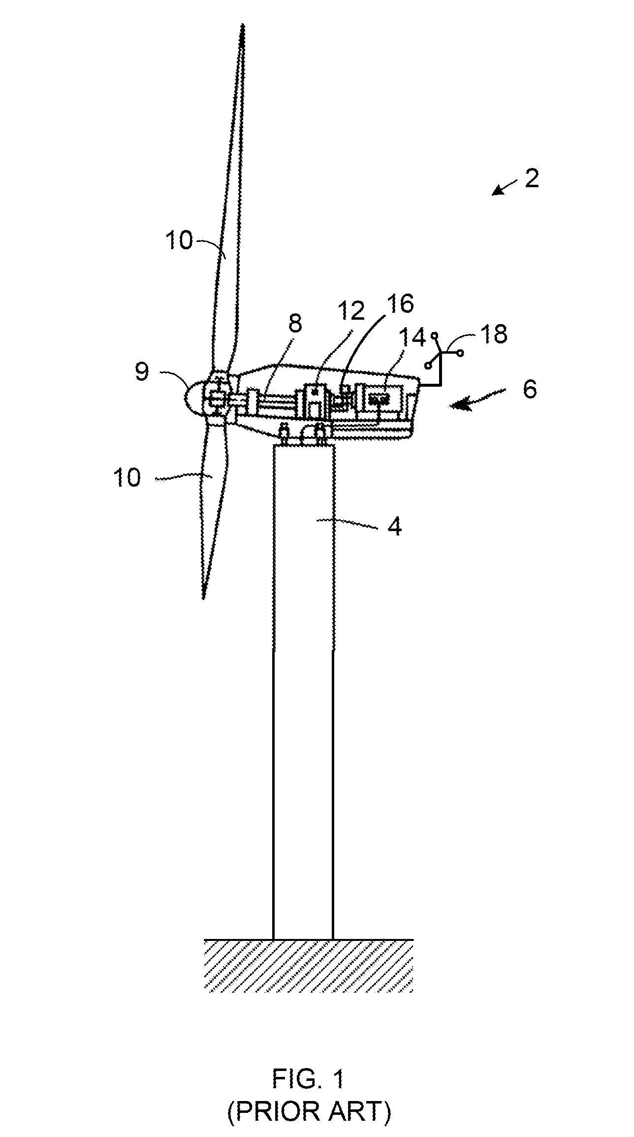
Wind turbines are subject to fluctuating forces which may cause deflections in various components.
These and other components of the wind turbine 2 that significantly bend or deflect as a result of those and / or other forces may eventually develop cracks that can lead to catastrophic failures.

Method used


Image

  • Wind turbine with GPS load control
  • Wind turbine with GPS load control
  • Wind turbine with GPS load control

Examples


Embodiment Construction

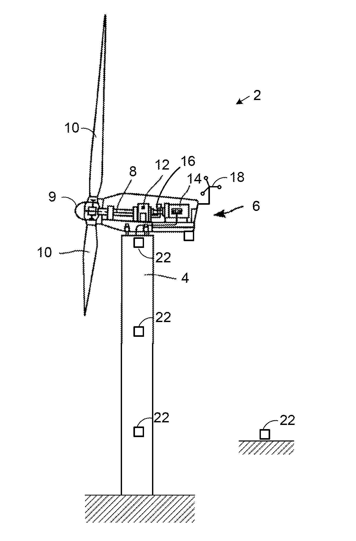
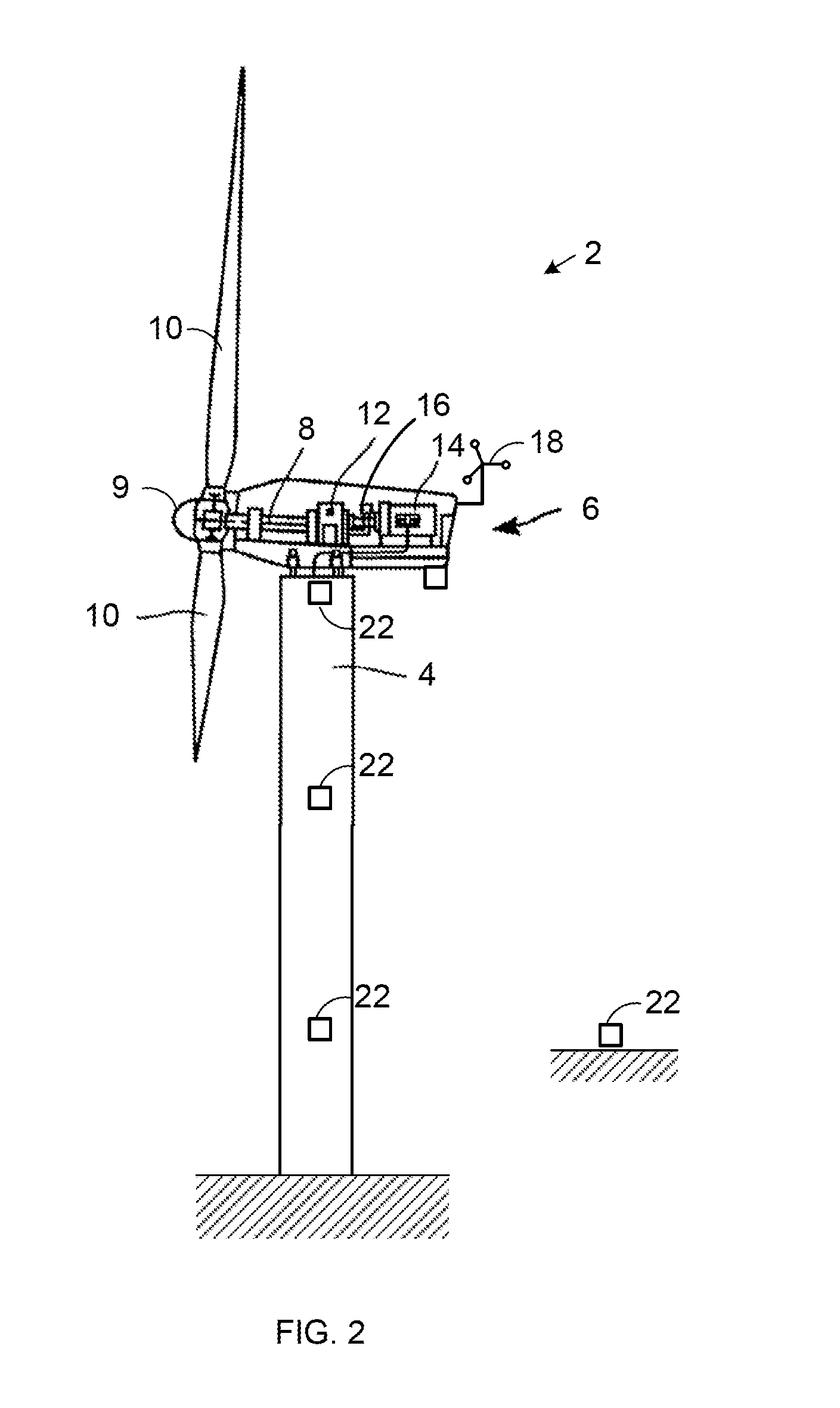
[0014]FIG. 2 is schematic side view of the wind turbine 2 from FIG. 1 having several position sensors 22. However, the technology describe here may also be used with any other wind turbine.

[0015]Some or all of the position sensors 22 may be arranged at various locations around the wind turbine 2, including but not limited to those illustrated here, for determining a deflection of a component of the wind turbine. For example, the position sensors 22 may be arranged on various stationary or moving components of the wind turbine 2 that bend, vibrate, or otherwise deflect during operation of the turbine 2, including, but not limited to, the tower 4, nacelle 6, hub 9, and / or blades 10. The position sensors 22 may be arranged at any location, including the points of expected maximum displacement of each component. For example, as illustrated in FIG. 3, the position sensors 22 may be arranged on any or all of the blades 10 at the span positions corresponding to the location of maximum defo...


PUM


Abstract

A wind turbine includes at least one global positioning sensor for determining a deflection of a component of the wind turbine.

Description

CROSS REFERENCE TO RELATED APPLICATIONS[0001]The subject matter disclosed here is generally related to commonly-owned, copending U.S. patent application Ser. No. ______ (Attorney Docket No. 233369) for “Wind Turbine Yaw Bearing Determination” by Timothy McCorkendale filed concurrently with this application and which is incorporated by reference here.BACKGROUND OF THE INVENTION[0002]1. Technical Field[0003]The subject matter described here generally relates to wind turbines, and, more particularly, to wind turbine load control using global positioning systems.[0004]2. Related Art[0005]A wind turbine is a machine for converting the kinetic energy in wind into mechanical energy. If the mechanical energy is used directly by the machinery, such as to pump water or to grind wheat, then the wind turbine may be referred to as a windmill. Similarly, if the mechanical energy is converted to electricity, then the machine may also be referred to as a wind generator or wind power plant.[0006]Win...

Claims


Application Information

Patent Timeline
IPC IPC(8): H02P9/04
CPCF03D11/0091F05B2270/33Y02E10/722F05B2270/807F05B2270/80F03D17/00
Inventor BENITO, PEDRO L.YEGRO, EUGENIO
Owner GENERAL ELECTRIC CO
Learn More