Multi-Stage Mechanical Delay Mechanisms For Electrical Switching and the like
a delay mechanism and multi-stage technology, applied in the direction of electric fuzes, weapons, ammunition fuzes, etc., can solve the problems of high labor intensity of thermal battery manufacturing process, large total displacement, and inability to operate in the non-operational condition of battery, so as to increase the shelf life and facilitate the manufacturing process. , the effect of large total displacemen
- Summary
- Abstract
- Description
- Claims
- Application Information
AI Technical Summary
Benefits of technology
Problems solved by technology
Method used
Image

Examples
embodiment 30
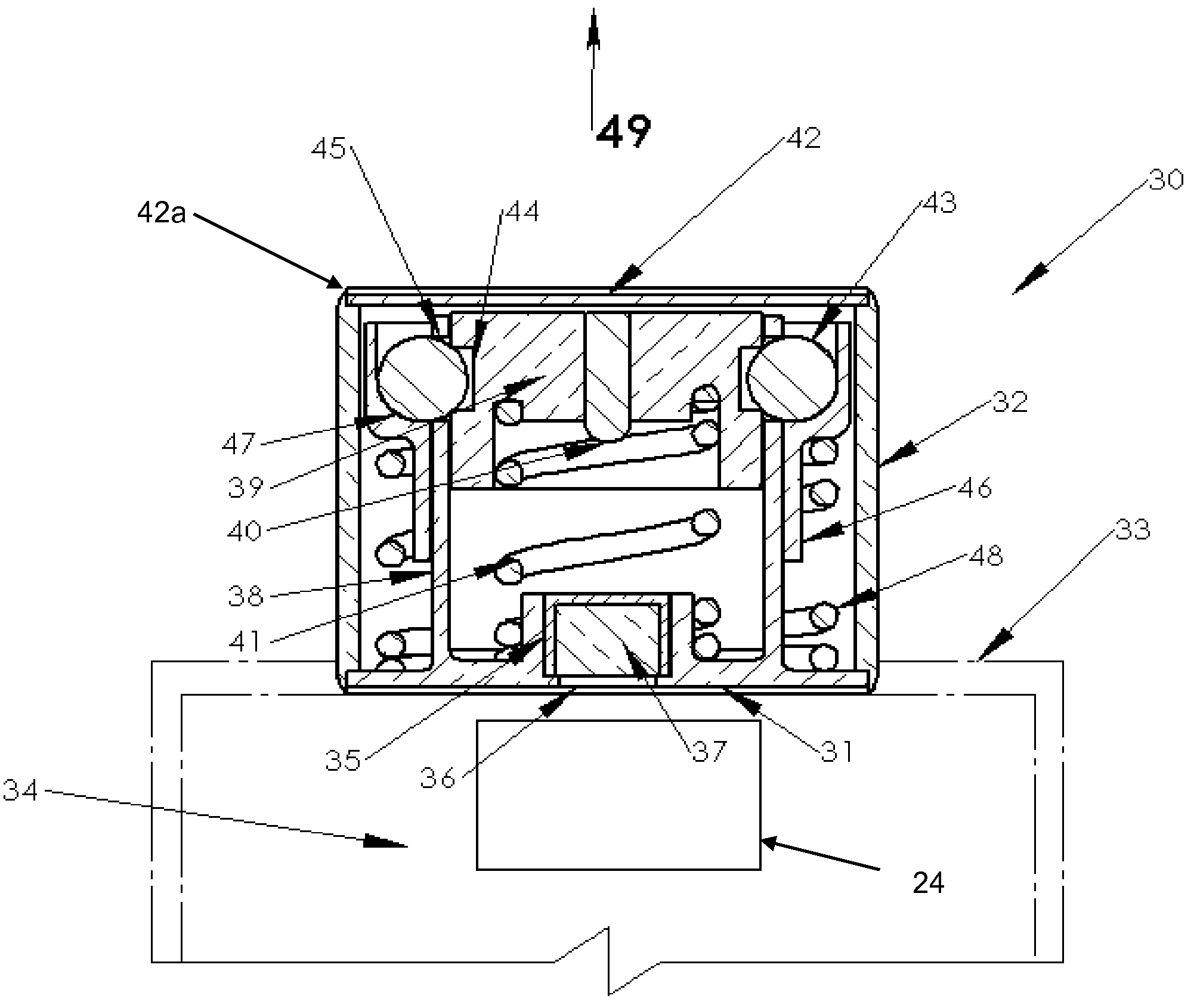
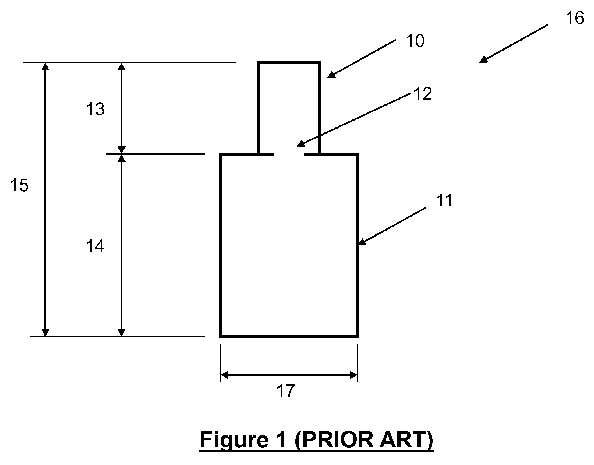
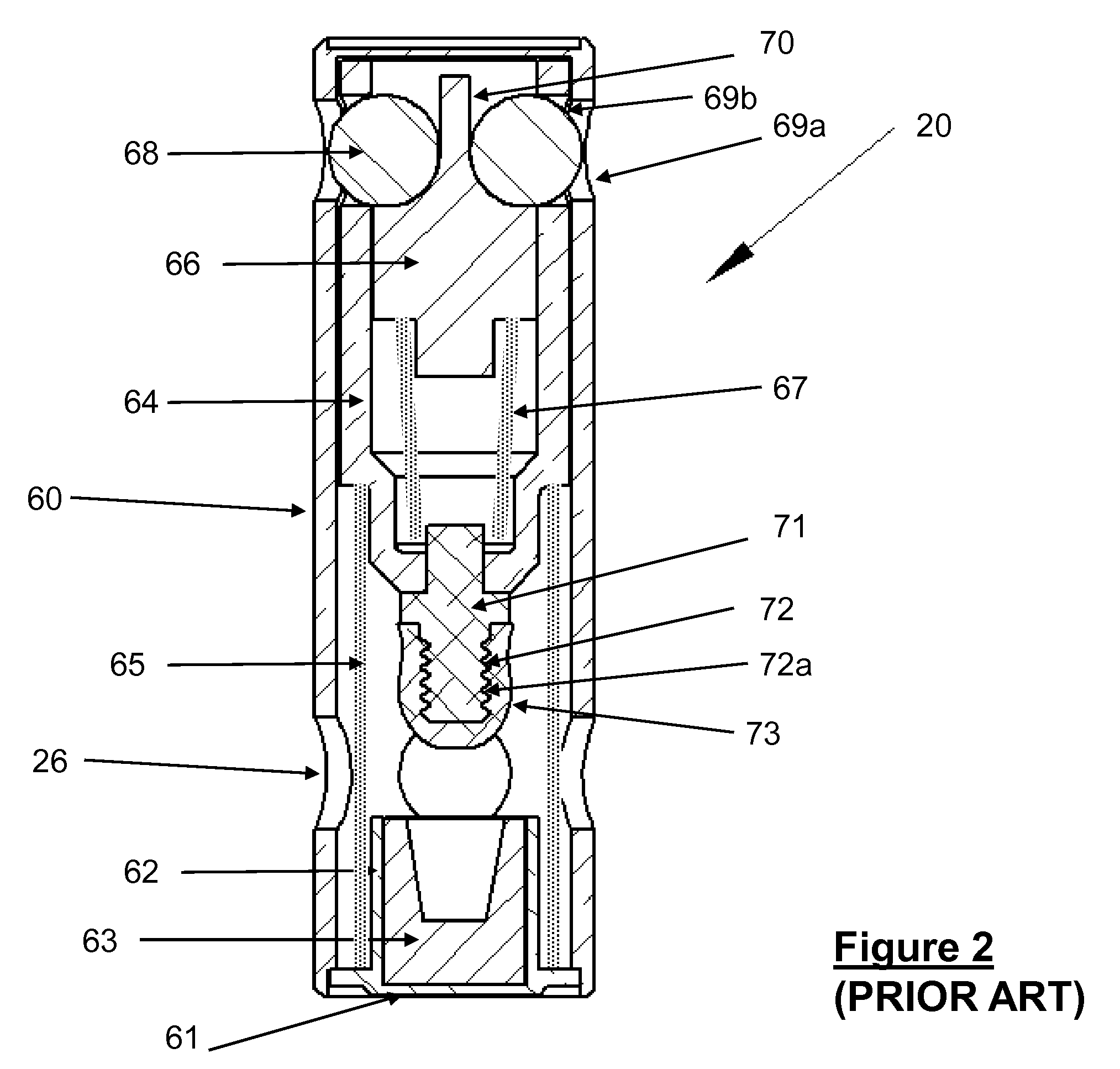
[0056]A schematic of an embodiment of an inertial igniter design which reduces the height of the inertial igniter component 13 (FIG. 1) is shown in FIG. 4. In such embodiment, the height 13 is reduced by over 45% as compared to the height required for the currently available igniters shown in FIG. 2 (see U.S. patent application Ser. No. 11 / 599,878, filed on Nov. 15, 2006, the contents of which is incorporated herein by its reference). In FIG. 4, the schematic of a cross-section of an embodiment 30 of the inertia igniter is shown, which is referred to generally with reference numeral 30. The inertial igniter 30 is constructed with an igniter body 31 and a housing wall 32. In the schematic of FIG. 4, the igniter body 31 and the housing wall 32 are joined together at one end; however, the two components may be integrated as one piece. In addition, the base of the housing 31 may be extended to form the cap 33 of the thermal battery 34, the top portion of which is shown with dashed lines...
embodiment 80
[0062]The novel method to achieve highly compact and long delay time mechanisms for miniature inertial igniters for thermal batteries and the like may be best described by the following “finger-driven wedge design,” which is a multi-stage mechanical delay mechanism embodiment and its basic operation. The schematic of such a three-stage embodiment 80 is shown in FIG. 5a. The device 80 can obviously be designed with as many fingers (stages) as is required to accommodate any delay time requirement and no-fire specifications commonly seen in gun-fired munitions or the like. The mechanism generally has three fingers (stages) 81, 82 and 83, each of which provides a specified amount of delay when subjected to a certain amount of acceleration (in the vertical direction of the arrow 89 as viewed in FIG. 5a). The fingers are fixed to the mechanism base 84 on one end. Each finger is provided with certain amount of mass and deflection resisting elasticity (in this case in bending). Certain amou...
embodiment 120
[0090]The schematic of another embodiment 120 of the present invention is shown in FIG. 8a. In FIG. 8b, the housing 130 of the mechanical delay mechanism 120 is removed to show its internal components. In this embodiment, a closed-profile carriage element 121 is used instead of an open profile delay wedge 85 of the embodiment of FIG. 5. The closed-profile carriage element 121 is constrained to longitudinal translation between the guides 127 and the bottom wall 129 and top wall 131 of the housing 130 of the mechanical delay mechanism 120. The closed-profile carriage element 121 provides an anti-back-drive multi-stage mechanical delay mechanism that operates in a manner similar to the embodiment of FIG. 5. With the provision of the closed-profile carriage element 121, the engaging fingers (stages), 123 and 124 and 125 and 126 in FIG. 8b, prevent the closed-profile carriage element 121 to translate along its longitudinal guides 127 if subjected to acceleration in the said direction. Th...
PUM
 Abstract
Description
Claims
Application Information
 - R&D
- Intellectual Property
- Life Sciences
- Materials
- Tech Scout
- Unparalleled Data Quality
- Higher Quality Content
- 60% Fewer Hallucinations
Browse by: Latest US Patents, China's latest patents, Technical Efficacy Thesaurus, Application Domain, Technology Topic, Popular Technical Reports.
© 2025 PatSnap. All rights reserved.Legal|Privacy policy|Modern Slavery Act Transparency Statement|Sitemap|About US| Contact US: help@patsnap.com