
Dental Instrumentation Unit

Active Publication Date: 2010-05-27
DENTAL EQUIP LLC D B A PELTON & CRANE
View PDF5 Cites 9 Cited by
  • Summary
  • Abstract
  • Description
  • Claims
  • Application Information

AI Technical Summary

Benefits of technology

[0003]Dental delivery systems are often configured with a series of holders into which hand pieces are placed for storage. The holders are normally slotted, each in the shape of a half circle or half cylinder that has an opening slot suitably sized to assure that the hand pieces can be placed in the holders. Commonly, the hand pieces are connected to supplies such as a water line, a pressurized source of air and partial vacuums. Other hand pieces may be electrically powered. Prior arrangements of holders and hand pieces have typically been of fixed design. For example, it is common for a delivery system to be configured for a typical user without an ability to customize to the needs of a particular procedure or to the preferences of a specific user. Further, even to the extent a system is suitable for one user, e.g., dental assistant, such systems are not readily convertible to easily accommodate users with different needs or preferences such that two or more persons may use the same unit, each with optimal convenience. Embodiments of the present invention provide for a dental assistant's unit which supports hand-held instruments used in dental procedures and that allows for interchangeability of instruments or for convenient cleaning of the unit by a user.

Problems solved by technology

Further, even to the extent a system is suitable for one user, e.g., dental assistant, such systems are not readily convertible to easily accommodate users with different needs or preferences such that two or more persons may use the same unit, each with optimal convenience.

Method used


Image

  • Dental Instrumentation Unit
  • Dental Instrumentation Unit
  • Dental Instrumentation Unit

Examples


Embodiment Construction

[0019]Before describing in detail the particular methods and apparatuses related to embodiments of the invention, it is noted that the present invention resides primarily in a novel and non-obvious combination of components. So as not to obscure the disclosure with details that will be readily apparent to those skilled in the art, certain conventional components (e.g., air and water supply lines) have been omitted or presented with lesser detail, while the drawings and the specification describe in greater detail other elements and steps pertinent to understanding the invention. Further, the following embodiments do not define limits as to structure or method according to the invention, but only provide examples which include features that are permissive rather than mandatory and illustrative rather than exhaustive.

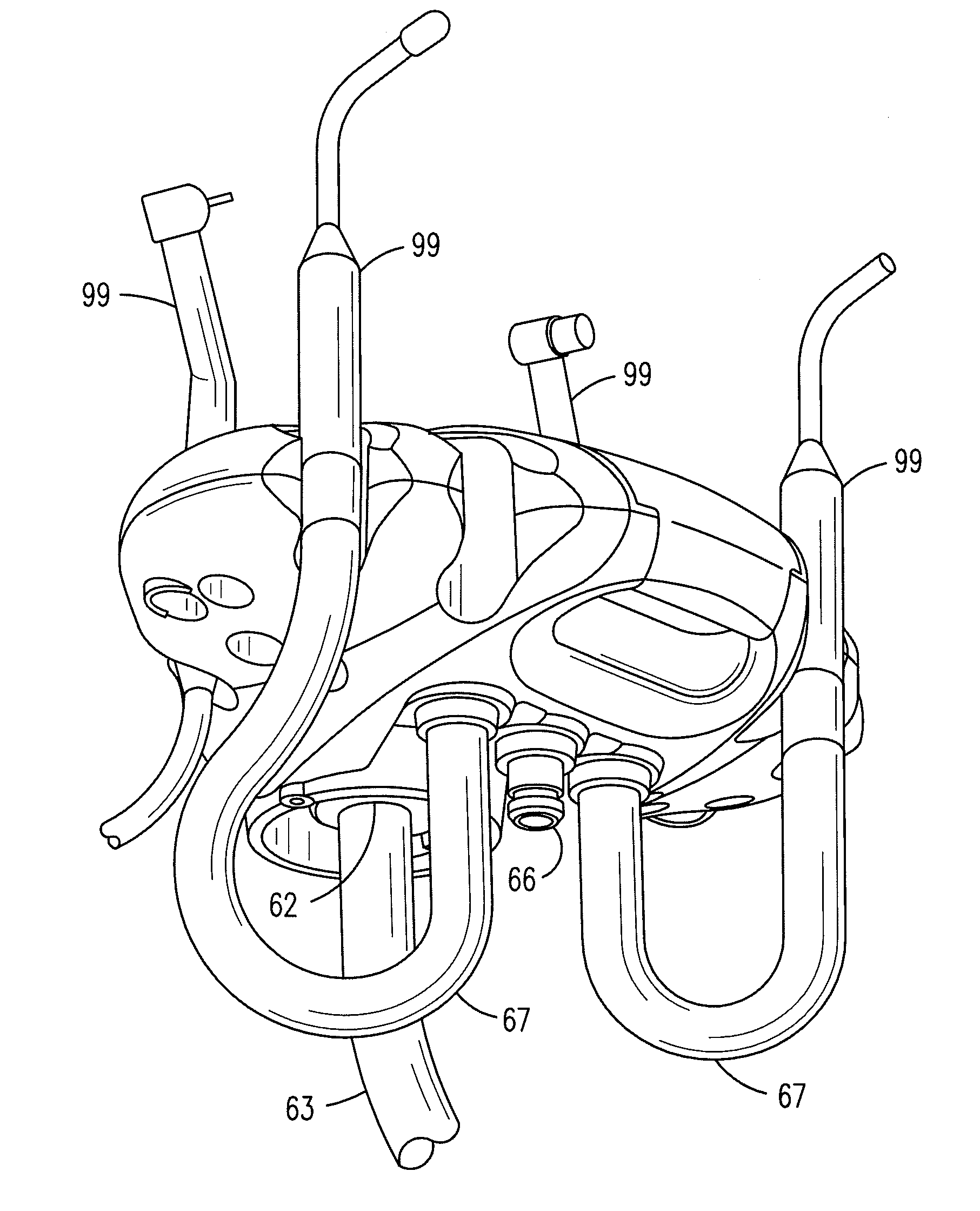
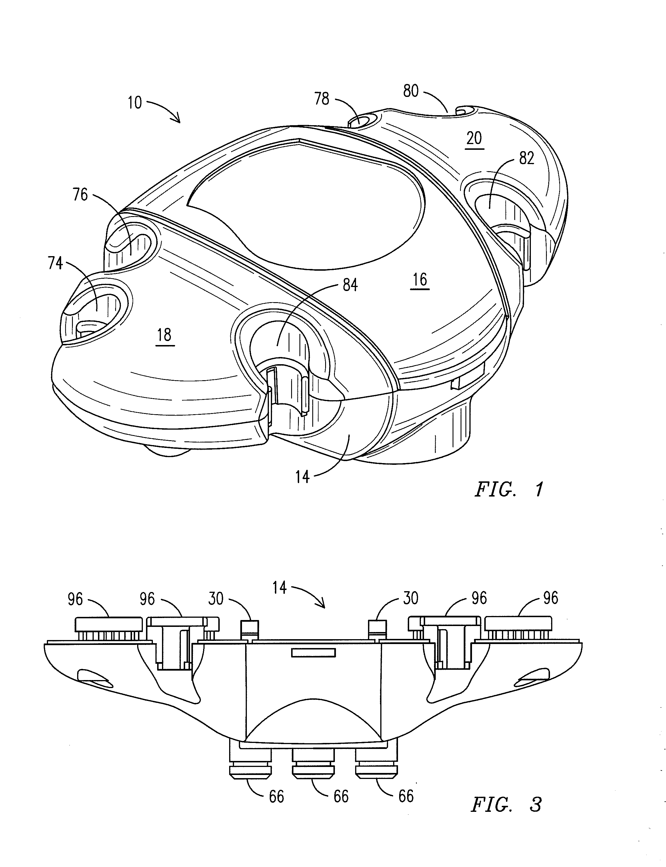
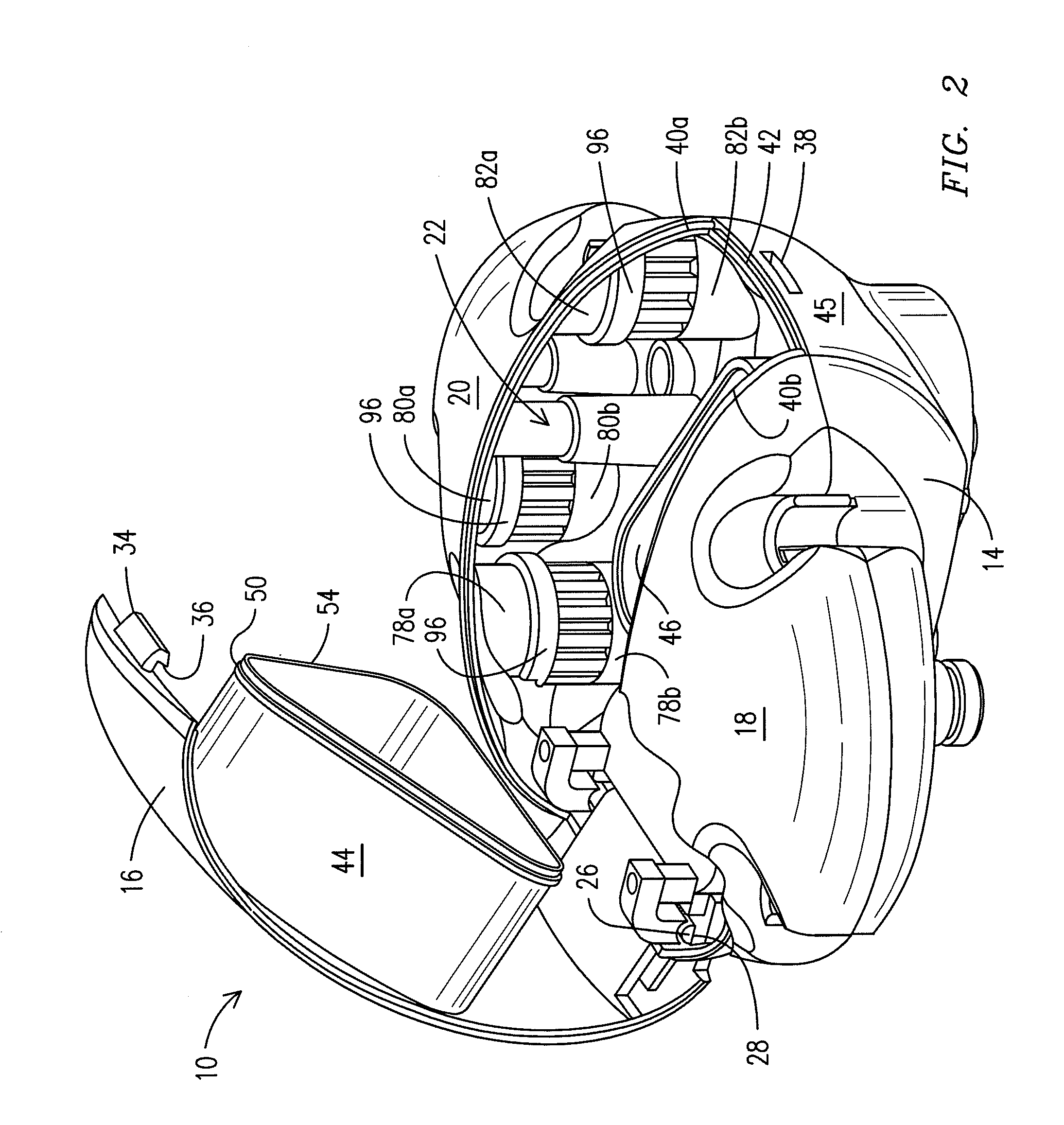
[0020]With reference to FIGS. 1 and 2, there is shown an instrumentation delivery unit 10 of the type which supports hand-held instruments such as used in dental procedur...


PUM


Abstract

An instrumentation delivery unit which supports hand-held dental instruments. In one example first and second housing members form a sealed chamber. When the members are separated, access is permitted to the interior of the chamber, e.g., for maintenance purposes. A first portal suitable for connection to a vacuum line provides a partial vacuum in the chamber, and second portals provide connection via second vacuum lines between the chamber and dental devices to operate the devices. The housing includes hand piece holders each of an initial diametric size for receiving hand pieces up to a maximum diametric dimension, with one of the hand piece holders formed along two adjoining ones of the housing members. The adjoining housing members secure inserts between one another to provide a second diametric size smaller than the initial diametric size to thereby selectably accommodate hand pieces having a smaller diametric dimensions.

Description

RELATED APPLICATION[0001]This application claims priority to provisional patent application U.S. 61 / 117,209, filed 23 Nov. 2008 which is incorporated herein by reference in the entirety.FIELD OF THE INVENTION[0002]This invention relates to dental operating equipment, and in described embodiments, relates more particularly to instrumentation units enabling interchangeability of equipment or convenient maintenance by a dental assistant.BACKGROUND AND SUMMARY OF THE INVENTION[0003]Dental delivery systems are often configured with a series of holders into which hand pieces are placed for storage. The holders are normally slotted, each in the shape of a half circle or half cylinder that has an opening slot suitably sized to assure that the hand pieces can be placed in the holders. Commonly, the hand pieces are connected to supplies such as a water line, a pressurized source of air and partial vacuums. Other hand pieces may be electrically powered. Prior arrangements of holders and hand p...

Claims


Application Information

Patent Timeline
IPC IPC(8): A61G15/00A61C17/08
CPCA61G15/16A61C17/06
Inventor BENFIELD, TOMBRIA, JOEHELGESEN, JOHNUNSWORTH, AUSTIN
Owner DENTAL EQUIP LLC D B A PELTON & CRANE
Learn More