Eureka AIR delivers breakthrough ideas for toughest innovation challenges, trusted by R&D personnel around the world.

Signal demodulation method based on dvb-s2

a signal demodulation and signal technology, applied in the field of demodulation technology, can solve the problems of inability to adapt the modulation method based on the same transmission method to meet the communication environment of every region, and inability to obtain accurate information

Inactive Publication Date: 2010-05-27
ELECTRONICS & TELECOMM RES INST
View PDF2 Cites 4 Cited by
  • Summary
  • Abstract
  • Description
  • Claims
  • Application Information

AI Technical Summary

Problems solved by technology

However, in a broadcasting environment, since a reception region is wide and a channel environment of the reception region varies, the adaptive modulation method based on the same transmission method is not capable of satisfying the communication environment of every region.
However, this RM decoding technology cannot obtain accurate information after signal demodulation is complete.
That is, when there is an error in a carrier wavelength, it is impossible to obtain accurate information.
Moreover, if the above 7 bits of information cannot be obtained in a cold start state, which is an initial mode of demodulation, then descrambling and recognition of pilot location information cannot be carried out, which makes it difficult to employ a pilot symbol for signal demodulation.

Method used


Image

  • Signal demodulation method based on dvb-s2
  • Signal demodulation method based on dvb-s2
  • Signal demodulation method based on dvb-s2

Examples


case 10

[0026]Ten cases of channel environment are as follows:[0027]Uncoded, Additive White Gaussian Noise (AWGN)[0028]Case 1[0029]Physical Layer Signaling Code (PLSC) Decoding, Rayleigh fading[0030]Case 2: fd,norm=1.56×10⁻⁵ (fc=21 GHz, BW=25 MHz, v=20 km / h)[0031]Case 3: fd,norm=1.78×10⁻⁴ (fc=12 GHz, BW=25 MHz, v=400 km / h)[0032]Case 4: fd,norm=3.11×10⁻⁴ (fc=21 GHz, BW=25 MHz, v=400 km / h)[0033]Case 5: fd,norm=1.56×10⁻³ (fc=21 GHz, BW=5 MHz, v=400 km / h)[0034]PLSC Decoding, Rician fading (K=15 dB)[0035]case 6: fd,norm=1.56×10⁻⁵ (fc=21 GHz, BW=25 MHz, v=20 km / h)[0036]Case 7: fd,norm=1.78×10⁻⁴ (fc=12 GHz, BW=25 MHz, v=400 km / h)[0037]Case 8: fd,norm=3.11×10⁻⁴ (fc=21 GHz, BW=25 MHz, v=400 km / h)[0038]Case 9: fd,norm=1.56×10⁻³ (fc=21 GHz, BW=5 MHz, v=400 km / h)[0039]PLSC Decoding, AWGN[0040]Case 10

[0041]Each of Cases 1-10 shows different RM decoding performance with respect to channel environment. In particular, in cases 2, 3, and 4, RM decoding performance reaches an error floor, and in cases 6, 7, ...


PUM


Abstract

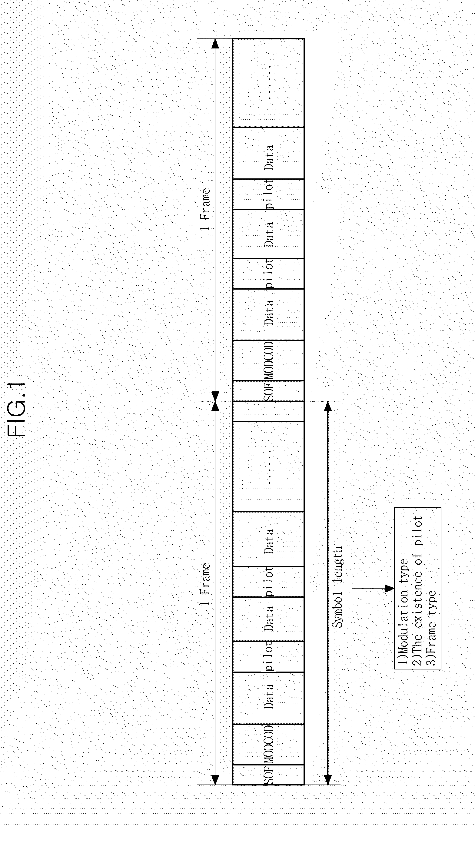
A satellite broadcasting frame signal demodulation method is disclosed. A demodulation method of a demodulator that demodulates a Digital Video Broadcasting-Satellite—Second Generation (DVB-S2) standard satellite broadcasting frame signal includes: performing symbol synchronization; performing frame synchronization after symbol synchronization; recovering a carrier wave after frame synchronization; and decoding mode code (MODCOD) information to obtain frame configuration information after recovering the carrier wave. This method ensures rapid demodulation and reliable demodulated data.

Description

CROSS-REFERENCE TO RELATED APPLICATION[0001]This application claims the benefit under 35 U.S.C. §119(a) of Korean Patent Application No. 10-2008-117066, filed on Nov. 24, 2008, the disclosure of which is incorporated herein in its entirety by reference.BACKGROUND[0002]1. FIELD[0003]The following description relates to demodulation technology, and more particularly, to frame signal demodulation technology in a transmission structure of a Digital Video is Broadcasting-Satellite—Second Generation (DVB-S2) system.[0004]2. Description of the Related Art[0005]In a DVB-S2 system, in order to maximize transmission efficiency, an Adaptive Coding and Modulation (ACM) method is used. In the ACM method, an optimal coding method and modulation rate are variably or adaptively selected according to channel state. By using this method, reception or linking of data by each receiver in a satellite broadcasting and telecommunication system is variably or adaptively controlled according to radio wave c...

Claims


Application Information

Patent Timeline
IPC IPC(8): H04L27/06
CPCH04L27/2655H04L27/2662H04L27/2657H04L27/2656H04N7/015
Inventor KIM, PAN-SOOCHANG, DAE-IG
Owner ELECTRONICS & TELECOMM RES INST
Why Eureka
Eureka Blog
Learn More