
Projection-type display apparatus and method for performing projection adjustment

a projection display and projection display technology, applied in the direction of printers, instruments, camera focusing arrangement, etc., can solve the problems of inability to disadvantageously fully serve the intended purpose of the guide display and the difficulty of visually recognizing the displayed contents of the guide display

Active Publication Date: 2010-05-27
SEIKO EPSON CORP
View PDF3 Cites 62 Cited by
  • Summary
  • Abstract
  • Description
  • Claims
  • Application Information

AI Technical Summary

Benefits of technology

[0006]An advantage of some aspects of the invention is to provide a technology that readily allows the user to visually recognize a guide display when the user performs install position adjustment and performs the install position adjustment so that a user's desired install position is achieved.
[0015]Since the projection-type display apparatus projects the calibration image simultaneously with the guide display image, the focus adjustment in which the guide display image is brought into focus can be performed in a short period.Third Application

Problems solved by technology

The projected image is therefore not in focus, which makes it difficult to visually recognize the displayed contents of the guide display.
As a result, the guide display cannot disadvantageously fully serve its intended purpose.
It has been therefore pointed out that only the guide display projected before the trapezoidal distortion is corrected does not allow the user to adjust the install position so that every image is projected in a user's desired projection position.

Method used


Image

  • Projection-type display apparatus and method for performing projection adjustment
  • Projection-type display apparatus and method for performing projection adjustment
  • Projection-type display apparatus and method for performing projection adjustment

Examples


first example

A. First example

A1. Overall Configuration of Projector

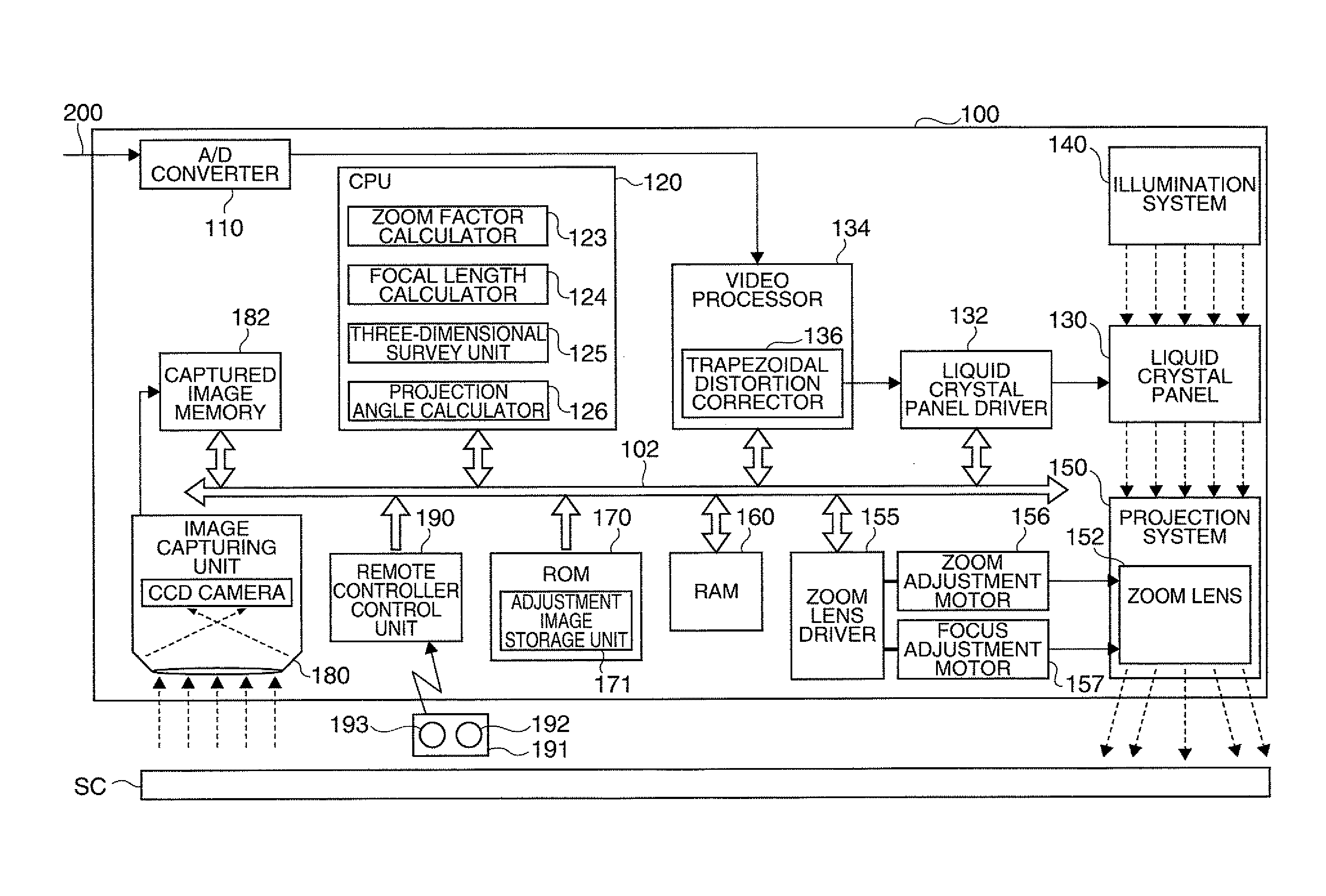
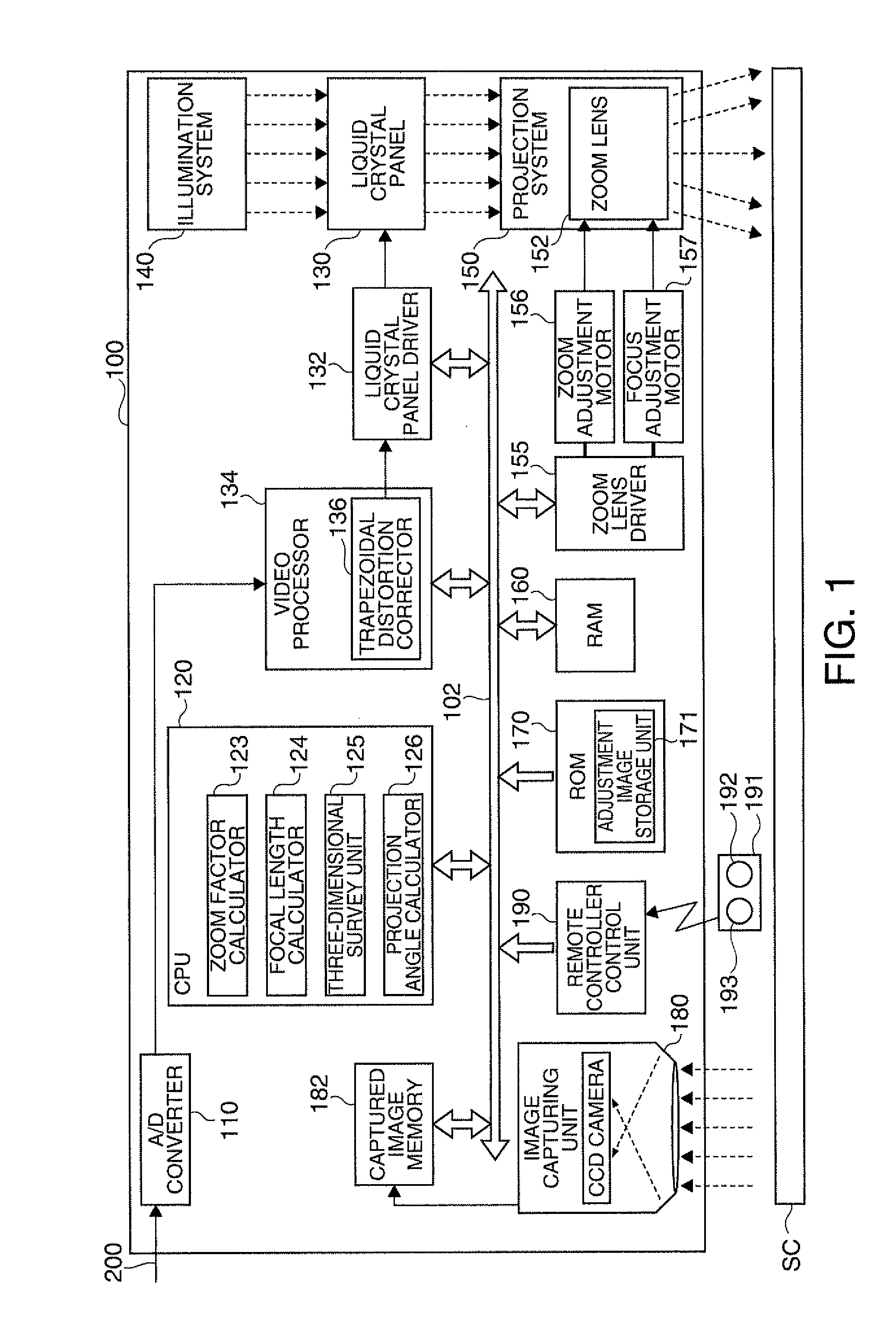
[0055]FIG. 1 is a block diagram showing an overall configuration of a projector 100 in a first example of the invention. The projector 100 externally receives an image signal representing an image and displays the image signal as the image (hereinafter referred to as a “projected image”) on a screen SC or any other suitable projection surface. In the present example, the screen plane has a rectangular shape.

[0056]The projector 100 can be roughly divided into an optical system that forms an optical image and an image processing system that electrically processes a video signal. The optical system includes an illumination system 140, a liquid crystal panel 130, and a projection system 150 and corresponds to the projection section in the claims. The illumination system 140 includes an arc lamp (not shown) and outputs the light from the arc lamp as the light used for projection. The liquid crystal panel 130 receives a signal from the...

second example

B. Second Example

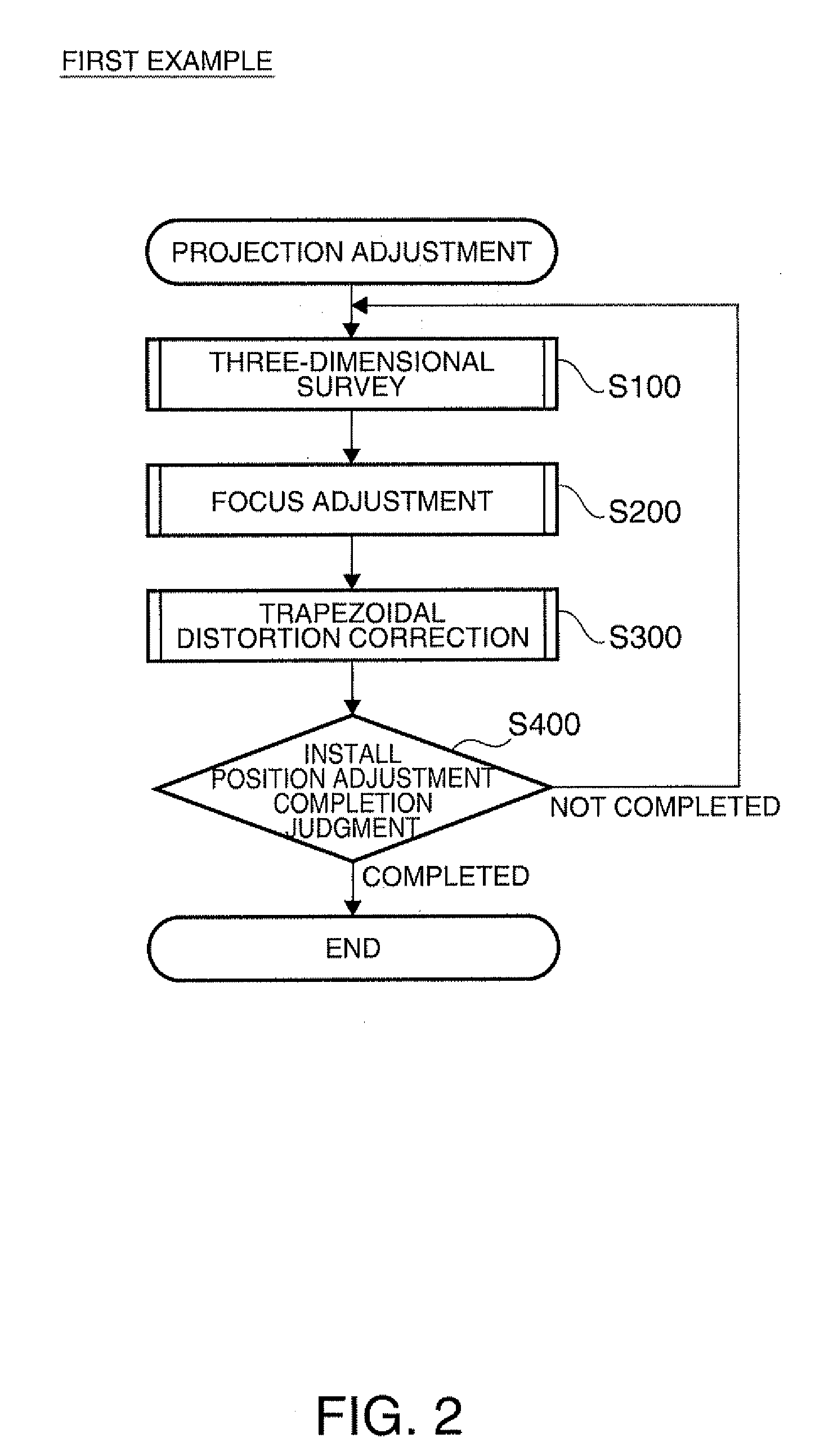
[0089]A second example will next be described. The second example differs from the first example in that the three-dimensional survey, the focus adjustment, the trapezoidal distortion correction, and the install position judgment are performed in a different order. Since the configuration of the projector and what is done in the three-dimensional survey, the focus adjustment, the trapezoidal distortion correction, and the install position judgment in the present example are the same as those in the first example, no detailed redundant description will be made.

[0090]FIG. 8 shows the procedure of the projection adjustment in the second example. The step labeled with a lower-case alphabetical character appended to the reference numeral indicates that the process in that step is the same as that in the step having the same reference numeral in the first example. First, the user operates the projection adjustment button 192 to initiate the projection adjustment. When the...

third example

C. Third Example

[0093]A third example will next be described. The third example differs from the first example, as in the second example, only in that the three-dimensional survey, the focus adjustment, the trapezoidal distortion correction, and the install position judgment are performed in a different order. Therefore, no detailed redundant description of the configuration of the projector and the processes performed in the projector will be made.

[0094]FIG. 9 shows the procedure of the projection adjustment in the third example. When the user's operation of the projection adjustment button 192 is detected, the CPU 120 initiates the projection adjustment routine shown in FIG. 9. When the projection adjustment is initiated, the three-dimensional survey (step S100c) is first performed. In the three-dimensional survey, the combined image 330 shown in FIG. 3A is projected on the projection surface, and a plane that approximates the screen is calculated. The CPU 120, which has calculate...


PUM


Abstract

A projection-type display apparatus that projects an image toward a projection surface and displays the image thereon, the apparatus includes: a projecting section that includes a focal length adjusting mechanism and projects an image; an adjustment image controlling section that uses the projecting section to project a guide display image suggesting how to adjust the position where the projection-type display apparatus is installed and uses the projecting section to project a calibration image having a predetermined shape when the guide display image is projected; a projection distance measuring section that measures a projection distance that is the distance to the projection surface based on a captured image obtained by capturing the calibration image; and a focus adjusting section that operates the focal length adjusting mechanism based on the projection distance to perform focus adjustment so that the displayed guide display image is brought into focus.

Description

BACKGROUND[0001]1. Technical Field[0002]The present invention relates to a projection-type display apparatus that projects an image toward a projection surface and a method for performing projection adjustment.[0003]2. Related Art[0004]There has been a known technology of performing trapezoidal distortion correction, focus adjustment, and other corrections and adjustments (hereinafter referred to as projection adjustment) on an image projected (hereinafter referred to as a “projected image”) by a projection-type display apparatus represented by a projector using a liquid crystal panel or any other suitable light modulator to form an image. To perform the projection adjustment, the projection-type display apparatus projects a guide display. The guide display is a display (such as characters and icons) that prompts a user to adjust the position where the body of the projection-type display apparatus is installed (hereinafter referred to as “install position adjustment”) so that a proj...

Claims


Application Information

Patent Timeline
IPC IPC(8): G03B21/14G03B3/00
CPCG03B21/26G03B21/53H04N9/3197H04N9/3185H04N9/3194H04N9/317
Inventor FURUI, SHIKI
Owner SEIKO EPSON CORP
Learn More