
Liquid crystal display device and viewing angle control panel

a technology of liquid crystal display device and control panel, which is applied in the direction of instruments, optics, non-linear optics, etc., can solve the problems of change cannot ensure privacy from other people, and not producing a sufficient

Active Publication Date: 2010-05-27
SHARP KK
View PDF6 Cites 69 Cited by
  • Summary
  • Abstract
  • Description
  • Claims
  • Application Information

AI Technical Summary

Benefits of technology

[0021]The present invention was accomplished in view of the above problems. It is an object of the present invention to provide a viewing angle control panel which allows an improvement of a blocking effect and to provide a liquid crystal display device including the same.
[0045]According to the above arrangement, it is possible to make a viewing angle narrower in the second viewing angle.

Problems solved by technology

However, this does not produce a sufficient effect.
However, such a change cannot ensure privacy from other people.
However, this does not produce a sufficient effect.
However, by such a technique, display contents cannot be sufficiently concealed in the wide viewing angle direction in a narrow viewing angle mode, and therefore other people can see the display contents.

Method used


Image

  • Liquid crystal display device and viewing angle control panel
  • Liquid crystal display device and viewing angle control panel
  • Liquid crystal display device and viewing angle control panel

Examples


Embodiment Construction

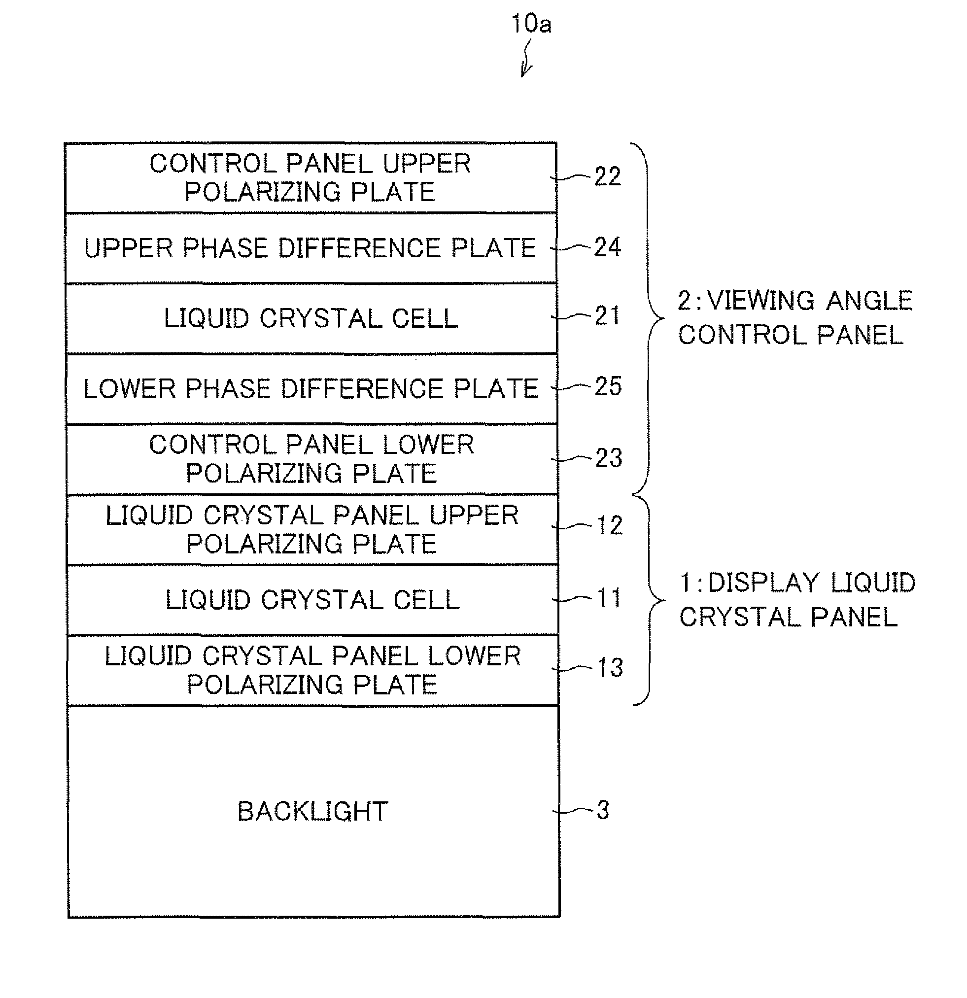
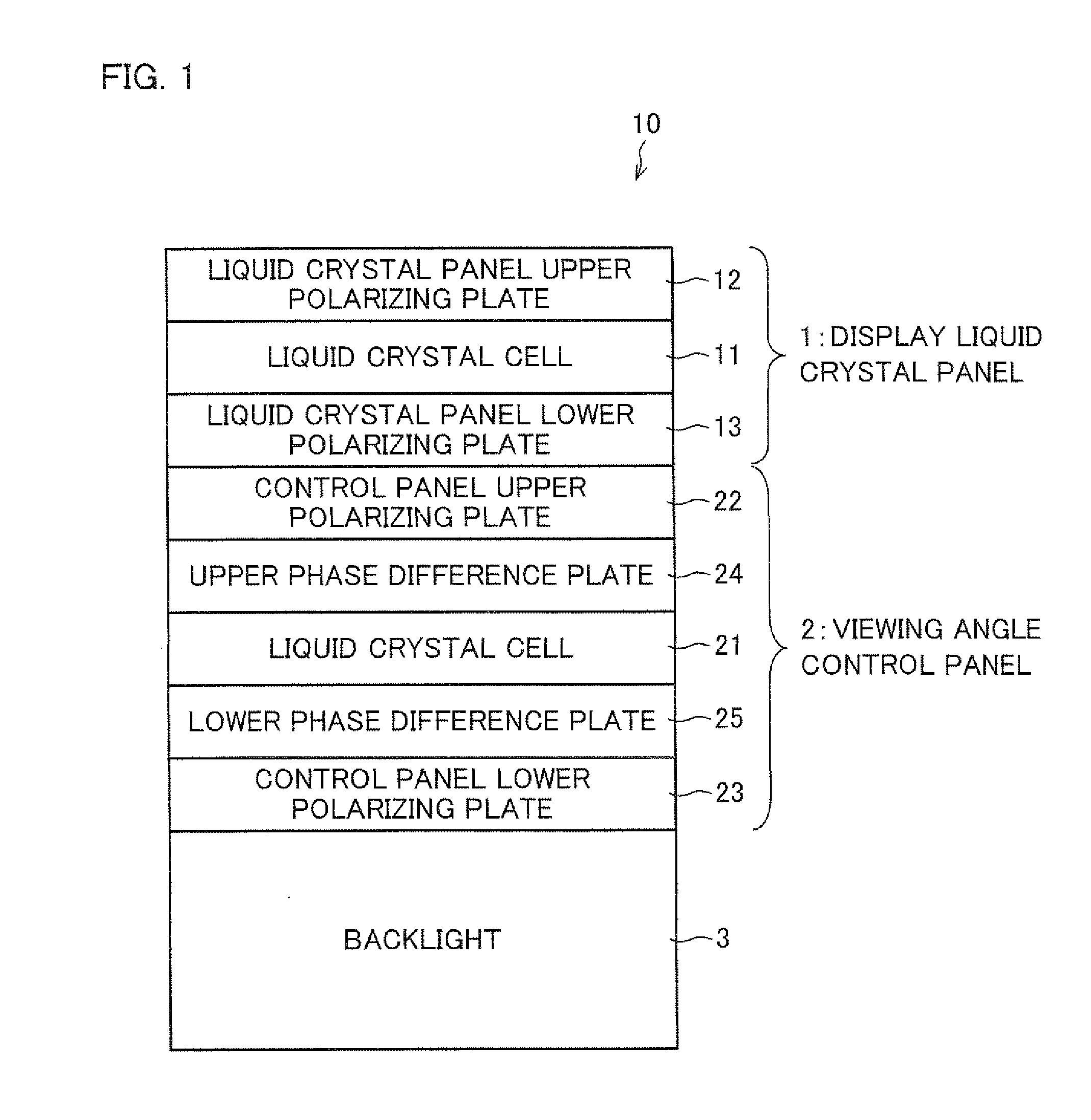
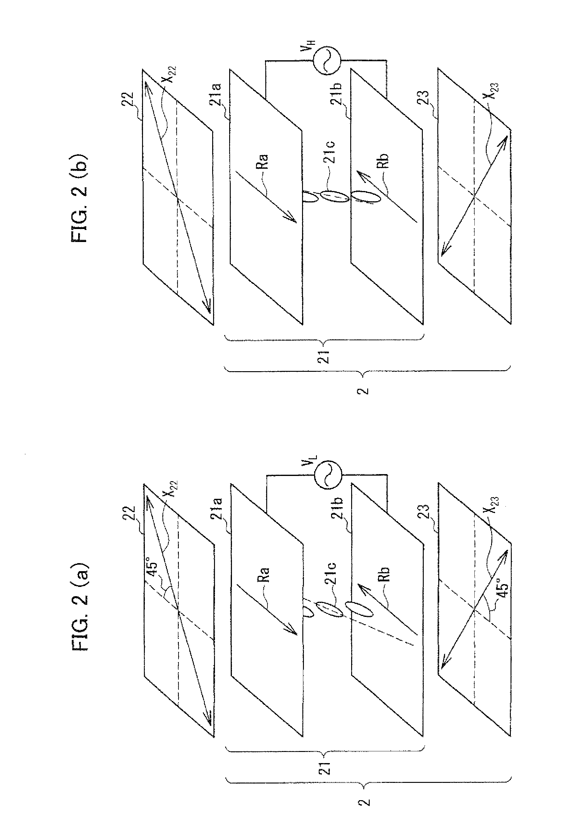
[0101]One embodiment of the present invention is described below with reference to FIGS. 1 through 15. It should be noted that the present invention is not limited to this.

[0102]Among constituent members of one embodiment of the present invention, only main members necessary for the explanation of the present invention are shown in the drawings for the easy explanation. Therefore, a liquid crystal display device of the present invention can include constituent members which are not shown in the drawings referred in the present specification. Further, the drawings do not illustrate the members in actual dimension and in actual dimensional ratios.

[0103]First, an arrangement of a liquid crystal display device 10 of the present embodiment is explained with reference to FIG. 1. FIG. 1 is a cross-sectional view showing an outline of an arrangement of the liquid crystal display device 10.

[0104]As shown in FIG. 1, the liquid crystal display device 10 includes two liquid crystal panels, that...


PUM

PropertyMeasurementUnit
angleaaaaaaaaaa
thicknessaaaaaaaaaa
thicknessaaaaaaaaaa

Abstract

A liquid crystal display device (10) of the present invention includes a backlight (3), a display liquid crystal panel (1) and a viewing angle control panel (2) for switching a viewing angle of the display liquid crystal panel (1) between a wide viewing angle mode and a narrow viewing angle mode. The viewing angle control panel (2) includes a control panel upper polarizing plate (22), a liquid crystal cell (21) and a control panel lower polarizing plate (23) stacked in this order, and phase difference plates (24, 25) are provided between the polarizing plates (22, 23) and the liquid crystal cell (21), respectively. The viewing angle control panel (2) is arranged such that Re1 in a white display portion in the wide viewing angle mode is nλ / 2 (n is an integer of 1 or more), Re2 in a white display portion in the narrow viewing angle mode is nλ / 2 (n is an integer of 1 or more), and Re3 in a black display portion in the narrow viewing angle mode is nλ (n is an integer of 1 or more).

Description

TECHNICAL FIELD[0001]The present invention relates to a viewing angle control panel for switching over a viewing angle of a display panel between a wide viewing angle and a narrow viewing angle and a liquid crystal display device including the viewing angle control panel.BACKGROUND ART[0002]Generally, a display device is required to have a viewing angle as wide as possible so that a clear image can be seen from any visual angle. Especially, in a liquid crystal display device which has been widely used in recent years, the liquid crystal itself has viewing angle dependency. Therefore, various techniques have been developed in order to increase the width of the viewing angle.[0003]However, in some environment, there is a case where it is preferable for a display device to have a narrow viewing angle so that only a user himself can see display contents. Especially, a notebook personal computer, PDA (Personal Data Assistant) or a mobile phone and the like are likely to be used in a plac...

Claims


Application Information

Patent Timeline
Patent Type & Authority Applications(United States)
IPC IPC(8): G02F1/13357G02F1/1347
CPCG02F1/1323G02F1/13363G02F1/1347G02F2413/12G02F2413/04G02F2413/08G02F2413/11G02F2001/133638G02F1/133634G02F1/133638C08J5/18G02F1/1335
Inventor MORISHITA, KATSUHIKOOKAZAKI, TSUYOSHISAKAI, TAKEHIKOKATAOKA, YOSHIHARUTSUKAMURA, CHIKANORICHIBA, DAI
Owner SHARP KK
Learn More