
Moving object

a technology for moving objects and objects, applied in the direction of vehicle position/course/altitude control, process and machine control, instruments, etc., can solve the problems of complicated construction of moving objects, limited size of step panels or the like, and restrictions on the design of moving objects, etc., to achieve simple construction, move stably, and move stably

Inactive Publication Date: 2010-05-27
TOYOTA JIDOSHA KK
View PDF20 Cites 20 Cited by
  • Summary
  • Abstract
  • Description
  • Claims
  • Application Information

AI Technical Summary

Benefits of technology

[0010]The invention provides a moving object having a simple construction may move stably regardless of whether the moving object is occupied.
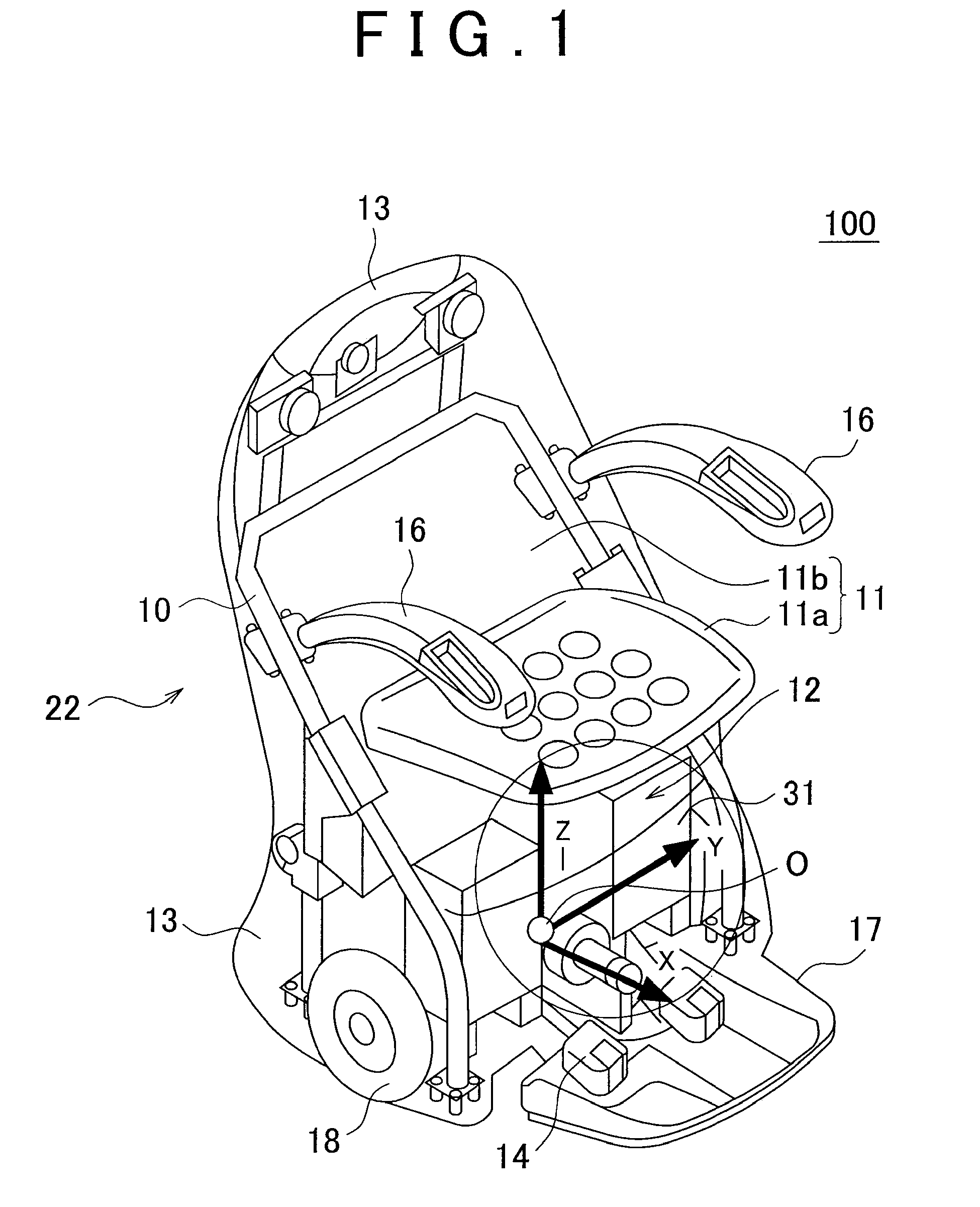
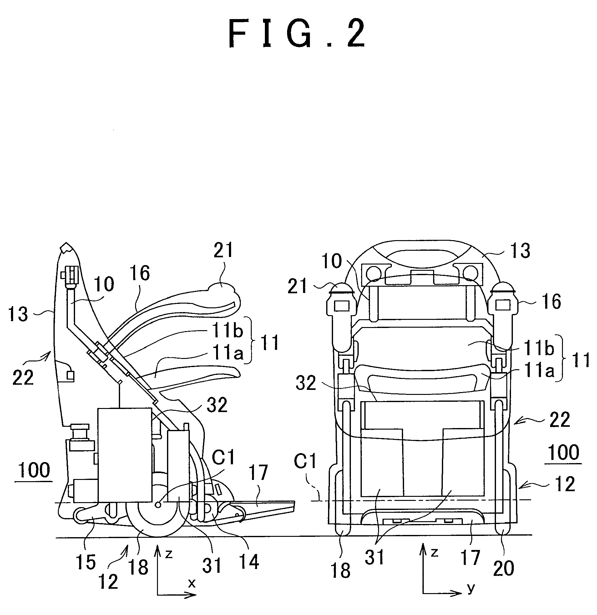
[0011]A moving object according to one aspect of the invention is a moving object that moves through inverted pendulum control, and is equipped with a passenger seat in which a passenger sits; a chassis disposed below the passenger seat; a wheel rotatably mounted on the chassis; a drive portion that rotationally drives the wheel; and a weight unit that is provided at least partially in front of an axle of the wheel. Thus, the angle of inclination of the moving object in an inverted state can be restrained from changing depending on whether or not the passenger sits therein. Accordingly, the moving object can maintain its balance in the longitudinal direction thereof, and may move stably with a simple construction regardless of whether or not the passenger sits therein.

Problems solved by technology

Thus, there is a restriction on the design of the moving object, and the size of the step panel or the like is limited.
Further, when the moving object is provided with a slide mechanism as described in Japanese Patent Application Publication No. 2006-205839 (JP-A-2006-205839), the construction of the moving object is complicated.

Method used


Image

  • Moving object
  • Moving object
  • Moving object

Examples


Embodiment Construction

[0017]A moving object according to this embodiment of the invention is an inverted wheel-type moving object that moves through inverted pendulum control. The moving object moves to a predetermined position through the driving of wheels on the ground. Furthermore, the moving object may be held inverted by driving the wheels in accordance with an output from a gyro sensor or the like. Further, the moving object moves in accordance with an amount of an operation performed by an operator while being held inverted.

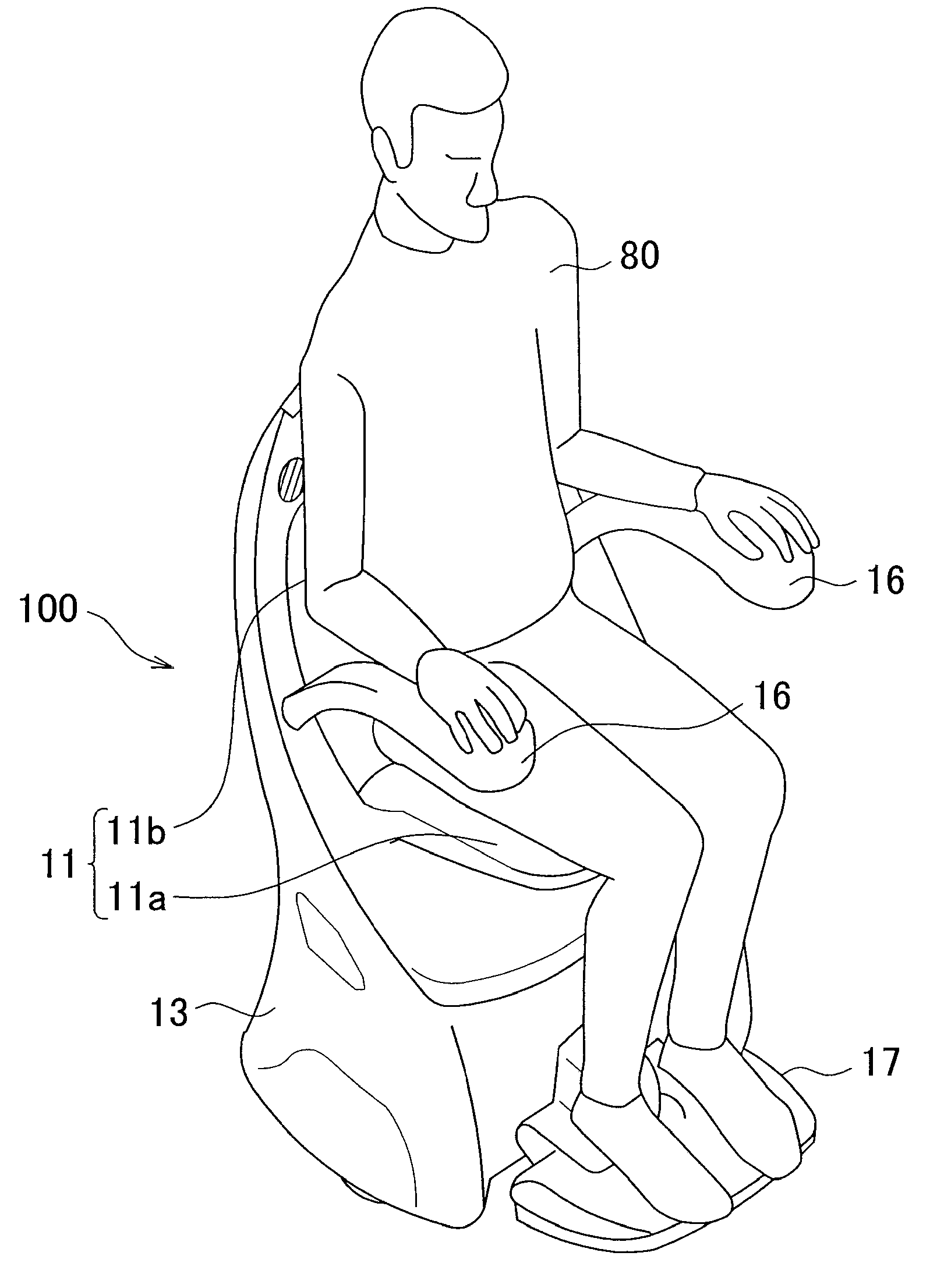
[0018]The construction of a moving object 100 according to this embodiment of the invention will be described using FIGS. 1 to 3. FIG. 1 is perspective view schematically showing the construction of the moving object 100. FIG. 2 is a view schematically showing the construction of the moving object 100, consisting of a lateral view on the left side and a front view on the right side. FIG. 3 shows a situation in which an occupant is seated in the moving object 100. It should be n...


PUM


Abstract

A moving object that moves through inverted pendulum control is equipped with a passenger seat in which a passenger sits, a chassis disposed below the passenger seat, a wheel rotatably mounted on the chassis, a drive portion that rotationally drives the wheel, and a weight unit that is provided at least partially in front of an axle of the wheel.

Description

INCORPORATION BY REFERENCE[0001]The disclosure of Japanese Patent Application No. 2008-302315 filed on Nov. 27, 2008 including the specification, drawings and abstract is incorporated herein by reference in its entirety.BACKGROUND OF THE INVENTION[0002]1. Field of the Invention[0003]The invention relates to a moving object, and more particularly, to a moving object that moves through inverted wheel control.[0004]2. Description of the Related Art[0005]In general, an inverted wheel-type moving object such as an inverted two-wheel vehicle or the like is controlled as to move while the position of a center of gravity of the moving object is modified to maintain the stability thereof by driving the right and left driving wheels. In addition, a construction for driving an inertial body provided above the wheels to stabilize an inverted state is described in, for example, Japanese Patent Application Publication No. 2006-205839 (JP-A-2006-205839). In the inverted wheel-type moving object, t...

Claims


Application Information

Patent Timeline
IPC IPC(8): B62D61/00B62D11/06
CPCA61G5/043A61G2005/125G05D1/0891B62D37/00B62D61/00A61G2005/128A61G5/125A61G5/128
Inventor KAWADA, NORIHIKO
Owner TOYOTA JIDOSHA KK
Learn More