
Coiled tubing bottom hole assembly with packer and anchor assembly

a packer and anchor assembly technology, applied in the field of downhole tools, can solve the problems of bha getting stuck in the wellbore, bha posing significant problems to any perforation, and fracturing operations

Active Publication Date: 2010-05-27
BAKER HUGHES INC
View PDF29 Cites 34 Cited by
  • Summary
  • Abstract
  • Description
  • Claims
  • Application Information

AI Technical Summary

Benefits of technology

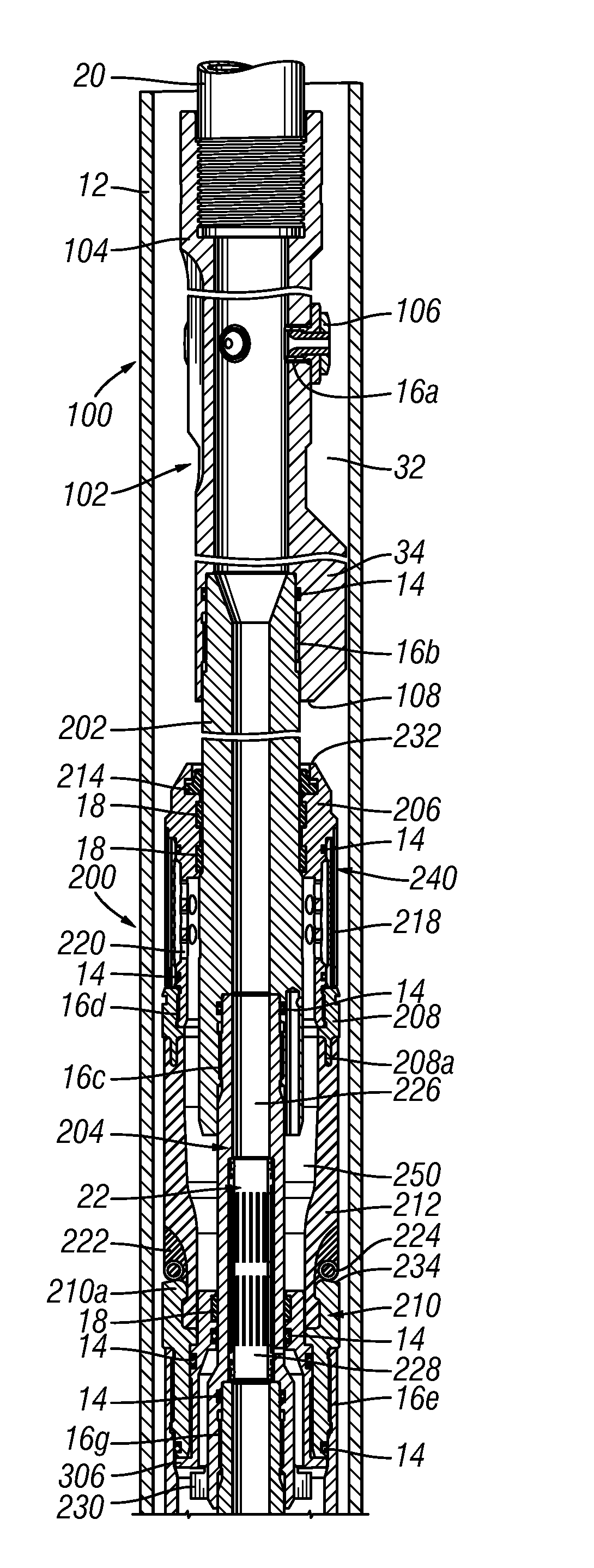
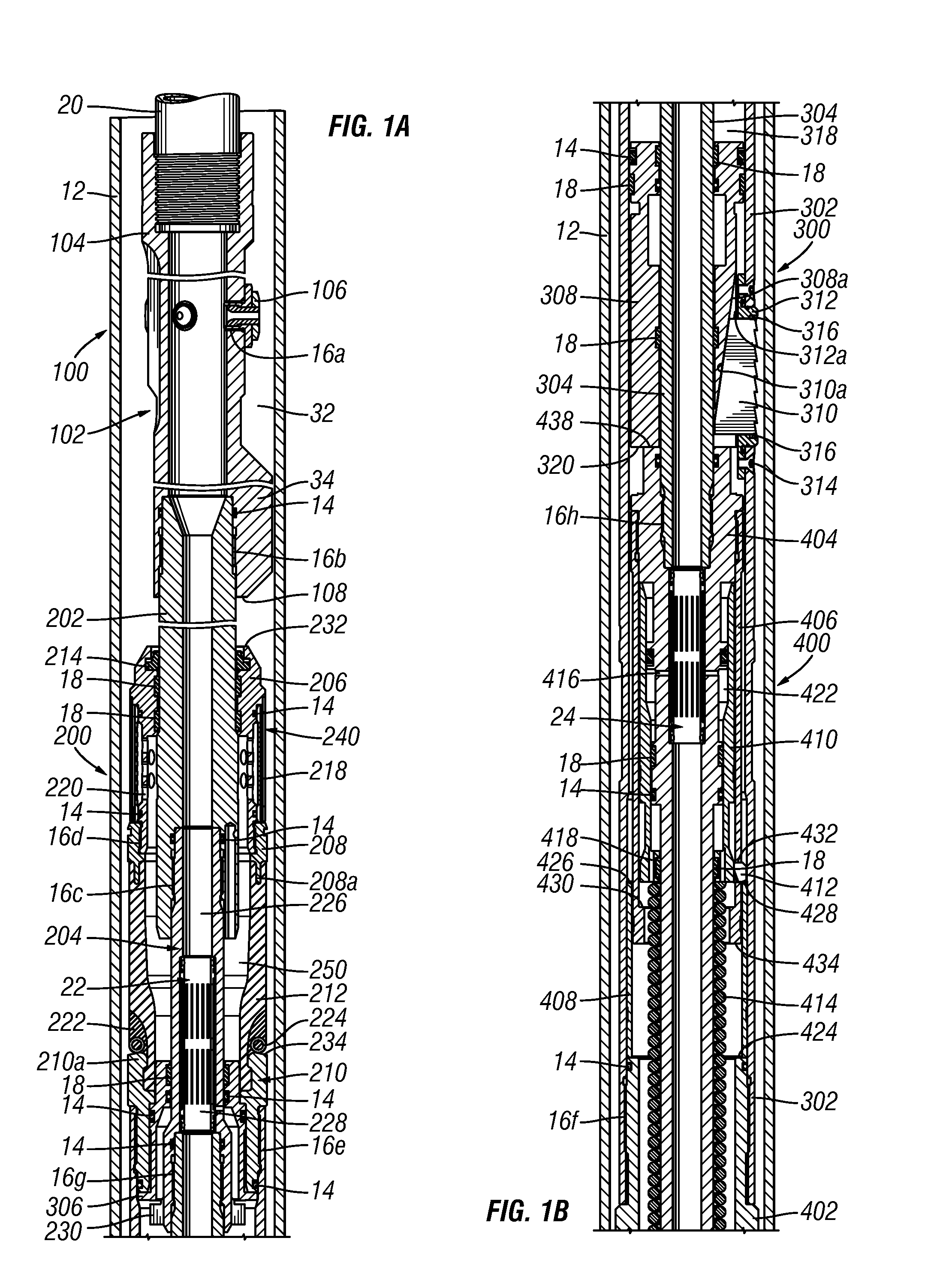
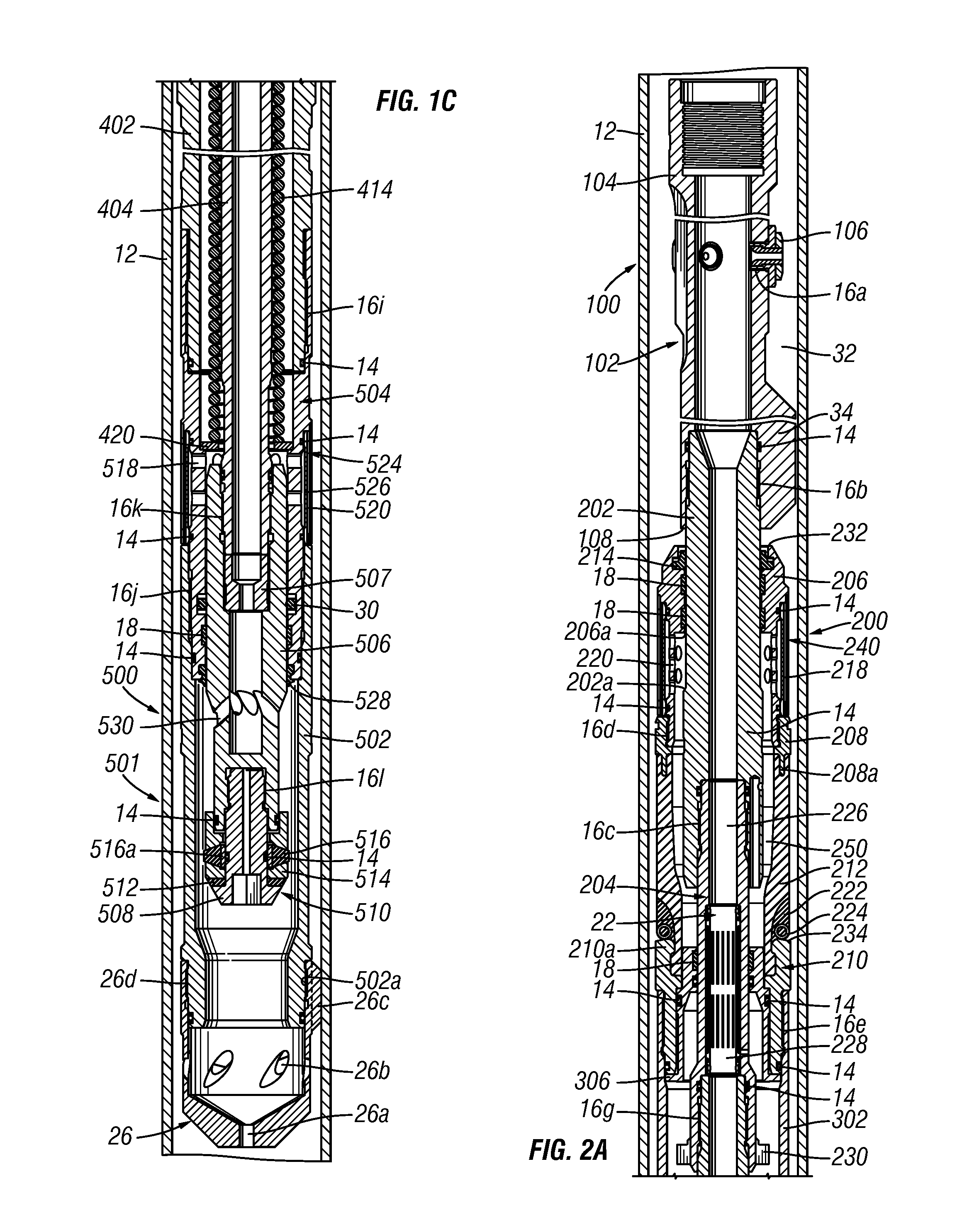
[0025]The packer assembly includes an upper packer mandrel connected to the perforating assembly and having a fluid path in communication with the fluid path of the perforating assembly. The packer assembly includes a packer filter housing slidably connected to the upper packer mandrel with the packer filter housing including flow ports in communication with an annulus between the coiled tubing and an internal surface of the casing. The packer assembly also includes a lower packer mandrel connected to the upper packer mandrel with the lower packer mandrel having a fluid path in communication with the fluid path of the upper packer mandrel. The packer assembly includes a lower packer crossover member, a first annular sealing element, and a second annular sealing element. The first annular sealing element is connected to both the packer filter housing and the lower packer crossover member, wherein a downward movement of the packer filter housing with respect to the lower packer crossover member engages the first annular sealing element with the internal diameter of the casing to create an initial seal. The second annular sealing element is connected to both the first annular sealing element and the lower packer crossover member and includes an embedded spring Annular pressure may communicate through the flow ports of the packer filter housing causing the first and second sealing elements to engage the internal surface of the casing to pressure-energize the initial seal.
[0035]In yet another illustrative embodiment, a method of isolating a portion of a wellbore is disclosed. The method includes positioning a BHA at a depth within a casing, activating an anchoring mechanism of the BHA by increasing a pressure differential within the BHA, and creating a seal against an interior surface of the casing by applying an axial mechanical force to the BHA. Increasing the pressure differential within the BHA may be accomplished by increasing a fluid flow rate within coiled tubing. Increasing the fluid flow rate may remove debris from between a BHA sealing element and an inner surface of the casing. The method may include performing a perforating operation on the interior surface of the casing after creating the seal against the interior surface of the casing by applying an axial mechanical force to the BHA. Activating the anchoring mechanism may include increasing the pressure within the BHA to drive an anchor housing in an axial direction and extending a plurality of anchor slips in a radially outward direction to engage with the interior surface of the casing in response to the axial movement of the anchor housing. Extending the plurality of anchor slips in a radially outward direction to engage with the interior surface of the casing may center the BHA within the casing. Creating a seal within the casing may include applying a mechanical force in a downhole direction onto the BHA to deform a first annular sealing element in an outward direction thereby engaging the interior surface of the casing, forming an initial seal with the casing and further increasing the pressure differential across the seal to pressure-energize the first annular sealing element, thereby pressure-energizing the initial seal. Extending the plurality of anchor slips may be triggered by increasing the pressure within the BHA. The method may further include disengaging the anchoring mechanism and releasing the seal. Disengaging the anchoring mechanism may include decreasing the pressure within the BHA. Disengaging the anchoring mechanism may include providing a mechanical force in an uphole direction to the BHA. Releasing the seal may include decreasing the pressure within the BHA.
[0037]Another embodiment of the present disclosure is a sand slurry valve that includes a housing, a mandrel, and a seal assembly connected to the mandrel. A portion of the housing includes a seal bore and the mandrel is movable within the housing such that the seal assembly may be positioned within the seal bore. The seal is adapted to provide a seal when positioned within the seal bore. The mandrel includes a flow passage that has been adapted to provide rotational fluid flow through the housing prior to the seal assembly being moved into the seal bore. The seal assembly may include a seal, a first backup ring, and a second backup ring with the second backup ring being positioned between the seal and the first backup ring. The rotational flow through the housing may help to protect the seal from being damaged by particles carried within the flow. The materials used in the components of the seal assembly may also be configured to protect the sealing element from damage due to particles within the housing. The first backup ring may have a harder durometer measurement than the second backup ring, which may have a harder durometer measurement than the sealing element. The first backup ring may be a thermoplastic, the second backup ring may be a fiber-filled Teflon, and the sealing element may be an elastomer.

Problems solved by technology

One challenge of performing fracturing operations with coiled tubing is due to the small clearances between the BHA and the casing.
Further, proppant used for fracturing may also lead to the BHA getting stuck within the wellbore.
A stuck BHA poses significant problems to any perforating and fracturing operation because of the resulting lost time and expensive specialized machinery and operating crews needed to retrieve the BHA.
Another challenge of performing fracturing operations with coiled tubing may be attributable to the relatively low strength of the coiled tubing.
Because only limited pulling forces are available through coiled tubing, it might not be possible to pull a stuck BHA out using coiled tubing.
Also the use of coiled tubing may present problems in setting the BHA within the wellbore.
However, coiled tubing cannot be used to transmit large axial forces, so such anchoring operations may be less effective if axial forces through the work string are required.
Conventional pressure set anchor systems are typically button type anchors, which may not adequately secure the BHA while properly centering the packing element, as discussed below.
One potential problem with the use of traditional compression set packers in coiled tubing applications is that, when such packers are employed, there is a very small radial clearance between the outside diameter of the packer assembly and the inside diameter of the casing.
The small radial clearance can present problems when trying to remove the BHA as discussed in detail below.
The use of proppants and / or cross linked gels in the fracturing fluid may increase the chance that the BHA becomes stuck in the wellbore due to the small clearances between the BHA and the casing.
In addition, the sealing elements in such compression set packers do not readily return to their original shape or size, or do so at a slow rate.
This further reduces the radial clearance between the packer assembly and the casing.
The relatively small clearance required by squashable sealing elements makes them potentially problematic for coiled tubing fracturing applications, as the packer is more likely to become stuck in the well.
Additionally, squashable sealing elements generally require large forces to axially compress the sealing element to sealingly engage the casing.
Some strategies can be employed to enable the use of squashable set packers with coiled tubing; however, in some applications coiled tubing cannot be relied upon to generate the required forces to set the squashable sealing element.
Therefore, because of the small clearances and large axial forces generally required to set a squashable sealing element, squashable sealing elements may not be acceptable for use in various coiled tubing applications.
Although such inflatable packers may have a relatively large clearance (e.g., 4″ ID casing, 3.125-3.5 OD packer), such inflatable packers may suffer from other potential problems.
When this occurs, the packer may not return to its original shape and size when it is deflated, or it may take a longer time to return to its original size and shape.
Although penetration of sand, proppant or other solids is not a concern with this type of an inflatable packer, a cord-type packer typically does not exhibit good recovery of its original shape in all applications.
Complete recovery of the inflatable elements of inflatable packers is a problem in general, particularly when such packers are subjected to repeated use under elevated temperatures and pressures typically experienced in a well.
Such lack of complete recovery may increase the chances of the tool getting stuck in the well.
The rubber sealing element, after unsetting, retains a larger outer diameter than it had prior to expansion, resulting in a greater chance that the BHA may become stuck in the casing.
This waiting period reduces the overall productivity of perforating and fracturing operations.
During the fracturing process, the large pressure differential on the set packer exerts a large force on the set anchor assembly.
In general, any packer assembly of a coiled tubing BHA is subject to inherent weaknesses of the coiled tubing.
That is, coiled tubing cannot transmit large amounts of axial forces to the packer and anchor assembly, and cannot be used to rotate the BHA relative to the casing.
In addition, the number of instances coiled tubing can be used to transmit forces at a determined depth is limited due to its low cycle fatigue life.

Method used


Image

  • Coiled tubing bottom hole assembly with packer and anchor assembly
  • Coiled tubing bottom hole assembly with packer and anchor assembly
  • Coiled tubing bottom hole assembly with packer and anchor assembly

Examples


Embodiment Construction

[0052]Illustrative embodiments of the present subject matter are described below. In the interest of clarity, not all features of an actual implementation are described in this specification. It will of course be appreciated that in the development of any such actual embodiment, numerous implementation-specific decisions must be made to achieve the developers' specific goals, such as compliance with system-related and business-related constraints, which will vary from one implementation to another. Moreover, it will be appreciated that such a development effort might be complex and time-consuming, but would nevertheless be a routine undertaking for those of ordinary skill in the art having the benefit of this disclosure.

[0053]The present subject matter will now be described with reference to the attached figures. The words and phrases used herein should be understood and interpreted to have a meaning consistent with the understanding of those words and phrases by those skilled in th...


PUM


Abstract

A bottom hole assembly (BHA), adapted to be positioned in a casing and to isolate a portion of a wellbore, which includes a packer assembly with a first sealing element extending between first and second portions of the packer assembly. A method of setting a BHA in a casing which includes increasing a BHA pressure to activate an anchor assembly, applying a mechanical force to mechanically deform a first sealing element to thereby establish an initial seal between the first sealing element and an interior surface of the casing, and increasing a pressure in a space between the BHA and the casing and in a cavity within the BHA to increase a differential pressure across the first sealing element and thereby establish a pressure-energized seal between the first sealing element and the interior surface of the casing.

Description

RELATED APPLICATIONS[0001]The present disclosure claims benefit of U.S. Provisional Patent Application No. 61 / 118,084, filed on Nov. 26, 2008, the disclosure of which is hereby incorporated by reference in its entirety.BACKGROUND[0002]1. Field of the Disclosure[0003]The present disclosure is generally directed to a downhole tool for use in oil and gas wells, and more specifically, to a coiled tubing bottom hole assembly with a packer and an anchor assembly for use in oil and gas wells containing solid-laden fluids. The packer and anchor assembly is particularly useful for isolating portions of a wellbore prior to fracturing oil and gas wells with coiled tubing.[0004]2. Description of the Related Art[0005]Perforating and fracturing operations have long been performed in completing oil and gas wells for production. Generally, perforating involves forming openings through the well casing and into the formation, by commonly known devices such as a perforating gun or sand jet. Thereafter...

Claims


Application Information

Patent Timeline
Patent Type & Authority Applications(United States)
IPC IPC(8): E21B23/01E21B29/00E21B33/12E21B33/1295E21B23/04E21B23/00E21B34/06E21B43/11E21B43/00
CPCE21B17/20E21B23/01E21B23/04E21B43/26E21B33/1295E21B34/06E21B43/114E21B33/128E21B23/0411E21B23/042
Inventor RAVENSBERGEN, JOHN E.
Owner BAKER HUGHES INC
Learn More