
Hybrid vehicle and control method thereof

a hybrid vehicle and control method technology, applied in the direction of process and machine control, instruments, etc., to achieve the effect of rapid rotation speed reduction

Active Publication Date: 2010-05-13
TOYOTA JIDOSHA KK +1
View PDF4 Cites 60 Cited by
  • Summary
  • Abstract
  • Description
  • Claims
  • Application Information

AI Technical Summary

Benefits of technology

[0007]In consideration of the problems described above, the invention provides a hybrid vehicle and a control method thereof, with which the hybrid vehicle can be allowed to continue traveling while suppressing secondary malfunctions when an abnormality relating to an internal combustion engine occurs.

Problems solved by technology

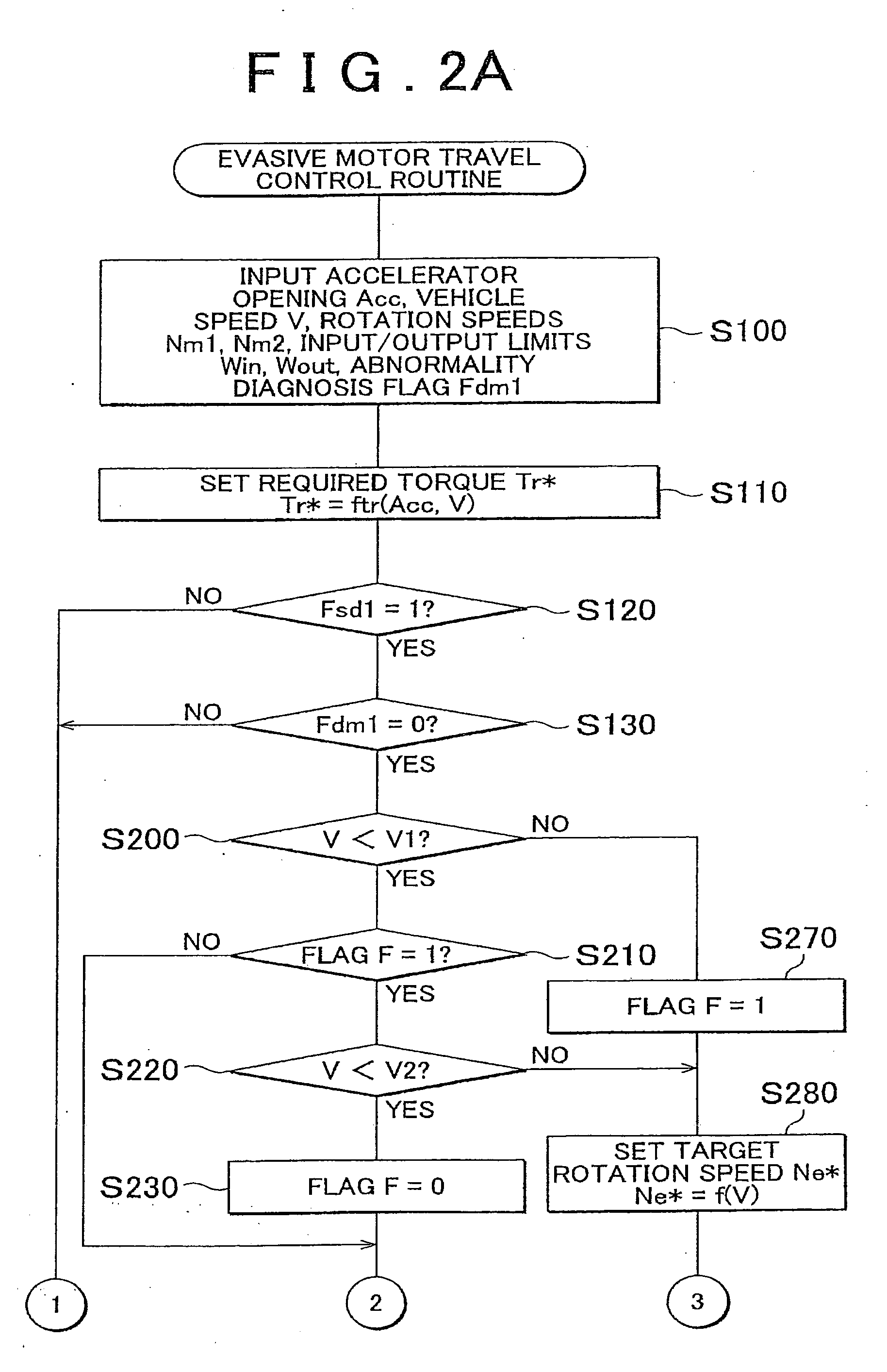
When the vehicle speed equals or exceeds the predetermined vehicle speed at a time of occurrence of an internal combustion engine-related abnormality, a rapid rotation speed reduction (rotation speed variation) in the internal combustion engine from a high vehicle speed state can be suppressed by motoring the internal combustion, engine using the first motor such that the engine shaft rotates at the predetermined target vehicle speed, and as a result, problems in the planetary gear mechanism and so on caused by rapid variation in the rotation speed of the internal combustion engine, a rapid increase to a reverse rotation side in the rotation speeds of the first element of the planetary gear mechanism and the first motor connected thereto, and so on can be suppressed favorably.

Method used


Image

  • Hybrid vehicle and control method thereof
  • Hybrid vehicle and control method thereof
  • Hybrid vehicle and control method thereof

Examples


Embodiment Construction

[0024]Next, an embodiment of the invention will be described.

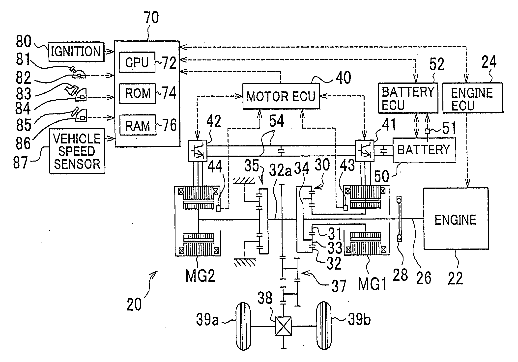
[0025]FIG. 1 is a schematic diagram showing a hybrid automobile 20 serving as a hybrid vehicle according to an embodiment of the invention. The hybrid automobile 20 shown in the drawing includes an engine 22, a triaxial power distribution integration mechanism 30 connected to a crankshaft (engine shaft) 26 of the engine 22 via a damper 28, a motor MG1 connected to the power distribution integration mechanism 30 and capable of generating power, a reduction gear 35 coupled to a ring gear shaft 32a that serves as a drive shaft and is connected to the power distribution integration mechanism 30, a motor MG2 connected to the reduction gear 35, a hybrid ECU 70 that controls the entire hybrid automobile 20, and so on.

[0026]The engine 22 is an internal combustion engine that outputs power upon reception of a supply of hydrocarbon-based fuel such as gasoline or light oil, and is subjected to control such as fuel injection amount co...


PUM


Abstract

The invention provides a hybrid vehicle and a control method thereof with which, in a case where a vehicle speed V obtained by a vehicle speed sensor equals or exceeds a first determination vehicle speed V1 at a time of occurrence of an internal combustion engine-related abnormality, which is when an abnormality relating to motors MG1 and MG2 is determined not to have occurred but an abnormality relating to an engine is determined to have occurred while the engine is operative, the motors MG1 and MG2 are controlled such that traveling torque is output to a ring gear shaft serving as a drive shaft from the motor MG2 while the engine is motored by the motor MG1 such that a crankshaft rotates at a target rotation speed until the vehicle speed V subsequently falls to or below a second determination vehicle speed V2.

Description

[0001]The disclosure of Japanese Patent Application No. 2008-286872, filed on Nov. 7, 2008, including the specification, drawings and abstract is incorporated herein by reference in its entirety.BACKGROUND OF THE INVENTION[0002]1. Field of the Invention[0003]The invention relates to a hybrid vehicle and a control method thereof.[0004]2. Description of the Related Art[0005]A conventional hybrid vehicle includes an engine, a planetary gear mechanism including a planetary gear that is connected to a crankshaft of the engine, a first motor connected to a sun gear of the planetary gear mechanism and capable of generating power, a second motor capable of outputting power to a ring gear shaft that serves as a drive shaft connected to a ring gear of the planetary gear mechanism, and a battery capable of exchanging power with the first and second motors (see Japanese Patent Application Publication No. 2003-32805 (JP-A-2003-32805), for example). In this hybrid vehicle, when an abnormality occ...

Claims


Application Information

Patent Timeline
Patent Type & Authority Applications(United States)
IPC IPC(8): G06F19/00F16H3/72B60K6/445B60K6/52B60K6/54B60L50/16B60W10/06B60W10/08B60W20/00F02D29/02
CPCB60L2240/486B60W2510/081B60W2540/12Y02T10/48B60W2710/083B60K6/365Y02T10/642Y10T477/26B60L2240/423B60K1/02Y10T477/24B60K6/445B60K6/547B60W20/00B60W2520/10B60W2710/0644Y02T10/6239B60W2540/10B60W10/08B60L2240/421B60W2540/16Y02T10/40Y02T10/62Y02T10/64B60W10/06B60W20/50
Inventor TAKAHASHI, SHIGENORITSUCHIYA, MITSUHIRO
Owner TOYOTA JIDOSHA KK
Learn More