
Cartridge Media Retention Mechanism

a media retention mechanism and cartridge technology, applied in the field of cartridges for printers, can solve the problems of affecting the quality of cartridges, affecting the reliability of cartridges, and reducing the risk of media jamming during printing or feeding, so as to minimize the risk of media jamming

Inactive Publication Date: 2010-05-13
BRADY WORLDWIDE INC
View PDF11 Cites 78 Cited by
  • Summary
  • Abstract
  • Description
  • Claims
  • Application Information

AI Technical Summary

Benefits of technology

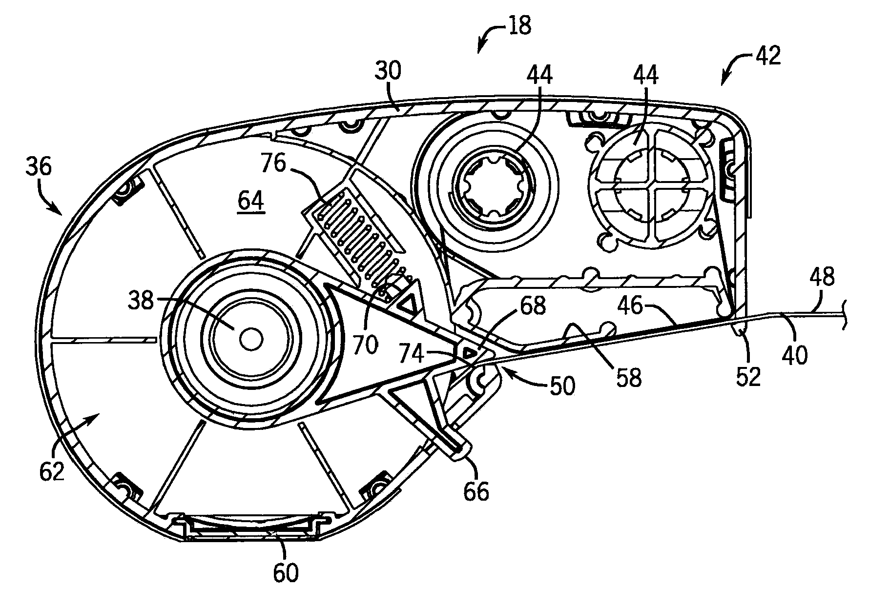
[0022]Thus, the disclosed media cartridge and associated retention mechanism provide an improved way of inhibiting the movement of a free end of a length of media when the cartridge is not loaded in a printer. Prior to the insertion of the cartridge in the printer or when the cartridge is removed from the printer, the retention mechanism inhibits the movement of the media. However, when the cartridge is inserted into the printer, the retention mechanism allows the media to be fed. With this design, the free end of the length of media is unlikely to recoil into the cartridge housing, rendering the cartridge unusable. Moreover, the retention mechanism helps to keep the end of the length of media in the media guides, so that during insertion of the cartridge into the printer, the media is properly threaded between the print head and the platen roller. This minimizes the risk of the media jamming during printing or feeding.

Problems solved by technology

Typically, it is difficult for a user to manually thread the media between the print head and a platen roller, given the small size of most handheld printers and the tight confines into which the media would need to be loaded.
However, storing the media in a cartridge also creates problems.
If the free end is pulled into the cartridge, then it is usually inaccessible and the cartridge is rendered useless.
If the free end is not guided properly past the print head and platen, then improper loading or feeding the media could jam the printer.
Hence, this solution does not accommodate the transfer of cartridges between printers or the switching of cartridges within a printer to change the type of media being printed on.
However, having a long path increases the footprint of the cartridge and increases the force required to feed the media.
This presents inefficiencies in feeding and marginalizes some of the benefit of reducing the size of the printer in the first instance.

Method used


Image

  • Cartridge Media Retention Mechanism
  • Cartridge Media Retention Mechanism
  • Cartridge Media Retention Mechanism

Examples


Embodiment Construction

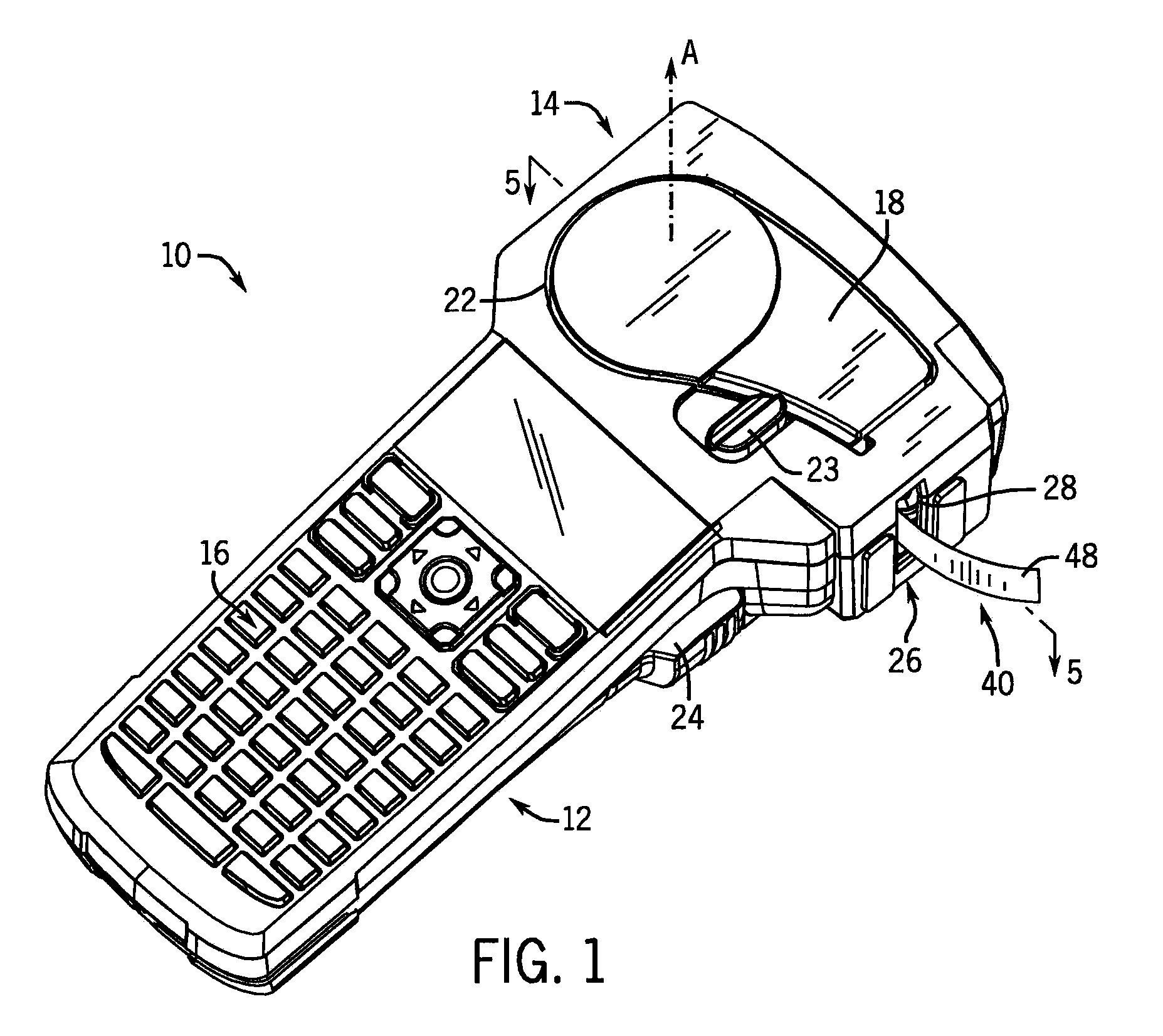
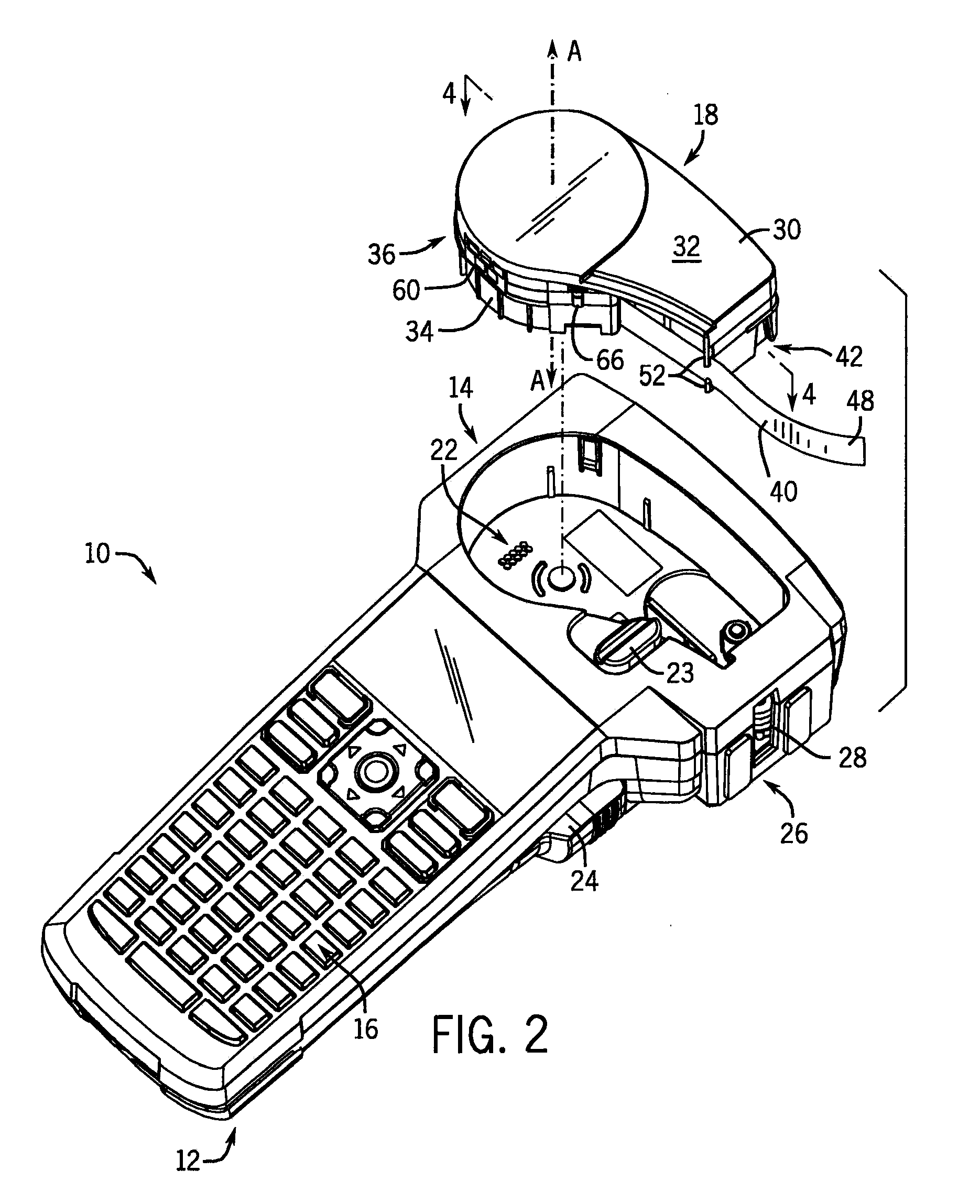
[0032]Referring first to FIGS. 1 and 2, a handheld printer 10 is shown. The handheld printer 10 has a body portion 12 and a head portion 14. The body portion 12 includes a keypad 16 for entering data and operating the handheld printer 10. On the lateral sides of the body portion 12 of the handheld printer 10 there are a pair of buttons 24. Preferably, the pair of buttons 24 are located on opposing sides of the handheld printer 10 such that the pair of buttons 24 can be actuated towards the body portion 12 and, at the same time, towards one another (by a pinching motion).

[0033]The head portion 14 is adapted to receive a cartridge 18. The cartridge 18 is removably received into a bay 22 in the head portion 14 of the handheld printer 10. A rotating lock 23 on the handheld printer 10 is used to retain the cartridge 18 within the bay 22.

[0034]Referring now to FIGS. 3-6, the various parts of the cartridge 18 can be seen. As best seen in FIG. 3, the cartridge 18 houses a roll 20 of printin...


PUM


Abstract

A media cartridge is disclosed for use in a printer that prints onto the media. The media cartridge includes a cartridge housing having an exit passage. The media cartridge has a length of media with an end extending from the exit passage. The media cartridge further includes a retaining arm having a pinch position and an open position. In the pinch position, the retaining arm impinges on the media in the exit passage to inhibit passage of the media through the exit passage. In the open position, the retaining arm allows passage of the media through the exit passage.

Description

CROSS-REFERENCE TO RELATED APPLICATION[0001]This application claims the benefit of U.S. Provisional Patent Application No. 61 / 113,124 filed Nov. 10, 2008, the disclosure of which is hereby incorporated by reference in entirety.STATEMENT OF FEDERALLY SPONSORED RESEARCH OR DEVELOPMENT[0002]Not applicable.BACKGROUND OF THE INVENTION[0003]This invention relates to cartridges for printers. In particular, this invention relates to retention mechanisms for preventing the undesired movement of media within the cartridge when the cartridge is not loaded in the printer.[0004]Handheld printers are used for printing applications in which portability and mobility are important considerations. Many such handheld printers are designed to receive cartridges containing rolls of media. This media may be, for example, adhesive-backed labels for application to documents, packages, and the like.[0005]Providing the media in cartridge form provides many benefits. One benefit is that the media can be prote...

Claims


Application Information

Patent Timeline
IPC IPC(8): B41J11/48
CPCB41J3/36B41J15/044B41J3/4075
Inventor FORD, THOMAS D. R.DUNN, ANTHONY R.
Owner BRADY WORLDWIDE INC
Learn More