
Voucher stacking apparatus

a stacking apparatus and stacking wheel technology, applied in the direction of thin material handling, article separation, article delivery, etc., can solve the problem that the space for stacking wheels that can be used as an alternative to stacking is relatively large, and achieve the effect of reliably and simple manner

Active Publication Date: 2010-05-13
DIEBOLD NIXDORF SYST GMBH
View PDF8 Cites 4 Cited by
  • Summary
  • Abstract
  • Description
  • Claims
  • Application Information

AI Technical Summary

Benefits of technology

[0005]An object of the invention is to propose an apparatus for stacking vouchers that enables notes to be transported reliably and in a simple manner.
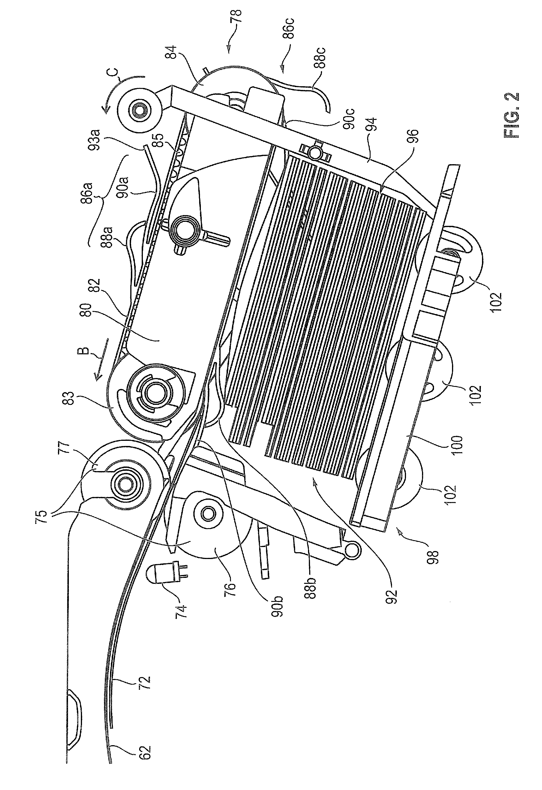
[0007]In an advantageous aspect of the invention, the transport tongue is lifted from the circumferential belt, and thus opened, by a voucher introduced into the transport tongue. In this open state of the transport tongue, the pressure tongue applies contact pressure to the transport tongue in the direction of the belt so that the voucher is pressed against the body of the circumferential belt by the transport tongue. As the result of this pressure, at least the adhesive friction between transport tongue and voucher is increased. In areas in which the stacking belt with the tongues on the body of the belt is radially deflected, the pressure tongue does not apply any contact pressure to the transport tongue. Rather, the pressure tongue can be lifted from the transport tongue and / or the transport tongue can be lifted from the voucher. As a result, it is possible to feed the voucher easily into the transport tongue as well as to extract the voucher easily from the transport tongue when the pressure tongue does not apply any contact pressure to the transport tongue, and / or when the transport tongue is lifted from the voucher.
[0008]In another aspect of the invention, at least two jockey rollers are provided to deflect the stacking belt radially. The stacking belt is guided over the at least two jockey rollers. As a result, it is a simple matter to effectuate lifting of at least one of the tongues, that is to say the pressure tongue is lifted from the transport tongue, or the transport tongue is lifted from the voucher or from the body of the belt. It is advantageous in this respect to connect at least one of the jockey rollers, secured against rotation, to a drive shaft for the purpose of driving the stacking belt. It is further advantageous to dispose several stacking belts adjacent one another across the width of the narrowest banknote that is to be stacked. Specifically, three stacking belts can be provided adjacent one another. It is advantageous in this regard if the stacking belts are disposed parallel to one another and are spaced equidistant from one another. The stacking belt, or the stacking belts respectively, preferably have three tongue pairs, wherein the tongue pairs are disposed at the same angular distance on the outer surface of the belt body. It is preferable if the inside of the stacking belt has serrations similar to the serrations of a cog belt. The slippage between a jockey roller configured as a drive roller and the stacking belt can thereby be reduced. Further, the jockey roller can have complementary serrations on its outer surface so that a positive connection exists between cog belt and jockey roller or drive roller.
[0010]It is advantageous to produce several stacking belts in one piece as a continuous tube, together with the tongue pairs disposed externally on the belt body. In this way, several stacking belts with almost identical properties can be produced after the tube is manufactured if the stacking belts are cut from said tube and are of the same width. Specifically, the stacking belts produced in this fashion have the same diameter. It is particularly advantageous if the retaining and pressure tongue and the transport tongue are respectively attached at different locations to the body of the stacking belt so that the area for attaching the retaining and pressure tongue to the belt body and the area for attaching the transport tongue to the belt body are spaced apart from each other in the direction in which the stacking belt circulates. It is advantageous in this regard to locate the retaining and pressure tongue downstream from the transport tongue when viewed in the direction of circulation.
[0013]It is particularly advantageous if the apparatus has at least one stop that halts the movement of the voucher occasioned by the stacking belts while the stacking belt continues to run. The voucher is withdrawn from the transport tongue. The retaining and pressure tongue of the tongue pair on the stacking belt is shaped such that, while the voucher is being transported with the aid of the stacking belt, a stack formed from the vouchers already deposited is kept at a distance by the retaining and pressure tongue. Through the contact of the retaining and pressure tongue with the top side of the stack, the retaining and pressure tongue is additionally pressed against the transport tongue, and a space is created between the voucher located in the transport tongue and the voucher located on the face of the stack facing the stacking belt. The feed of the voucher located in the transport tongue is not hampered as a result, and contact pressure on the voucher is increased.

Problems solved by technology

In contrast, the stacking wheels that can be used as an alternative for stacking require a relatively large space.

Method used


Image

  • Voucher stacking apparatus
  • Voucher stacking apparatus
  • Voucher stacking apparatus

Examples


Embodiment Construction

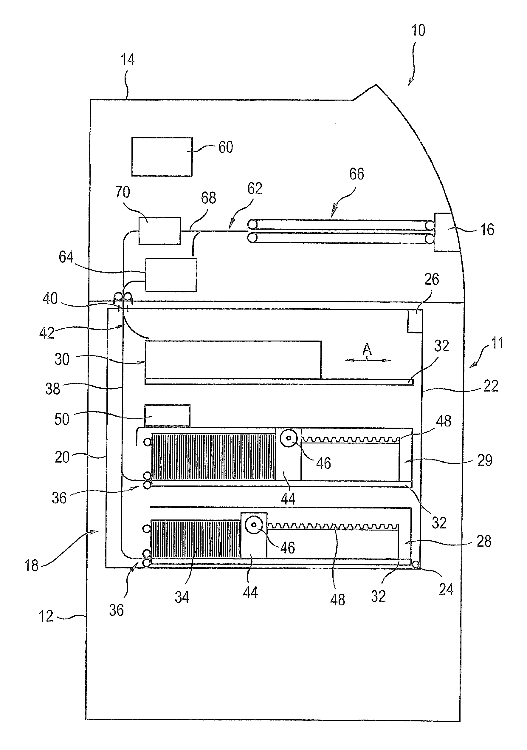
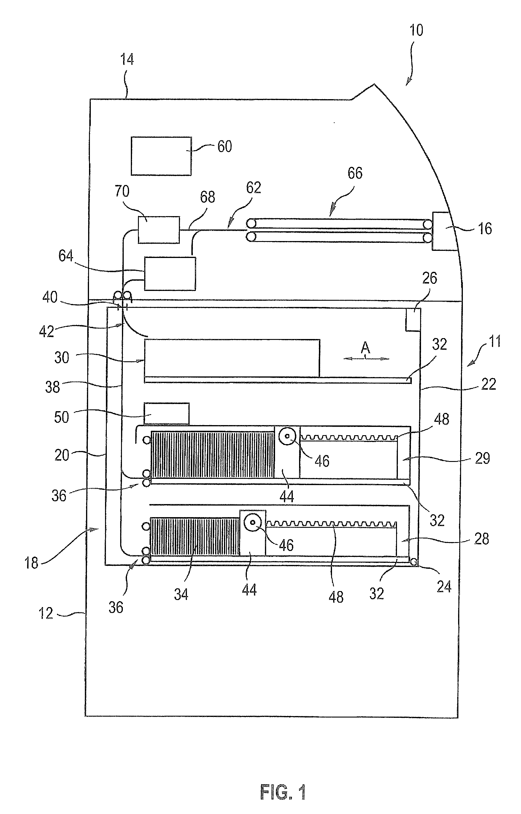
[0021]A vertical section through an automated teller machine 10 is shown in FIG. 1 with a housing generally identified with the numeral 11. The housing encompasses a cabinet-like lower part 12 and a housing upper part 14 set upon said lower part 12.

[0022]The functional units required for processing and for depositing and dispensing banknotes as well as for operating the automated teller machine 10 are located in the housing upper part 14. Said units encompass a display unit (not shown) and an input unit (also not shown) in addition to a dispensing drawer 16.

[0023]A safe 18 is located in the housing lower part 12 that has a box-shaped safe container 20 and a safe door 22 connected to said container. The safe door 22 is attached to the safe container 20 by a hinge 24, and can be pivoted into an open position and into a closed position and secured by a lock 26.

[0024]In the embodiment shown, a total of three banknote cassettes 28, 29, 30 are located in the safe 18, where cassettes 28 an...


PUM


Abstract

The invention relates to an apparatus for stacking vouchers that has at least one circumferential stacking belt (82). The stacking belt (82) has a circumferential belt body and at least one tongue pair (86a to 86c) provided outwardly on the belt body. The tongue pair (86a to 86c) has a transport tongue (90a to 90c) and a pressure tongue (88a to 88c). The pressure tongue (88a to 88c) and the transport tongue (90a to 90c) are configured and disposed such that the pressure tongue (88a to 88c) applies contact pressure to the transport tongue (90a to 90c) in the direction of the belt body at least in a circumferential area of the stacking belt (82).

Description

BACKGROUND OF THE INVENTION[0001]1. Technical Field[0002]The invention relates to a voucher stacking apparatus having at least one circumferential stacking belt that has a circumferential belt body and a transport tongue for accommodating at least one part of the voucher.[0003]2. Discussion[0004]A plurality of stacking systems for vouchers is known in which stacking belts are used. A system for stacking banknotes in banknote cassettes with the aid of a stacker and singulator module is known, for example, from the previously unpublished German patent application DE 10 2008 018 935.9. However, with known stacking belts only a relatively low contact pressure can be applied to the banknote located in the transport tongue, resulting in the banknote possibly slipping at least partially from the transport tongue. As a result, an uneven stack can be created or a paper jam can occur, caused by the banknote that was partially pulled from the transport tongue.SUMMARY OF THE INVENTION[0005]An o...

Claims


Application Information

Patent Timeline
IPC IPC(8): B65H1/08B65H3/34B65H1/00
CPCB65H29/048B65H31/02B65H83/02B65H2701/1912B65H2404/154B65H2404/2311B65H2404/692B65H2404/1114
Inventor FREITAG, PAULNOTTELMANN, ULRICHSCHNELLE, WILFRIED
Owner DIEBOLD NIXDORF SYST GMBH
Learn More