
Sheet folding apparatus

Active Publication Date: 2012-01-05
NISCA KK
View PDF9 Cites 17 Cited by
  • Summary
  • Abstract
  • Description
  • Claims
  • Application Information

AI Technical Summary

Benefits of technology

[0015]As described above, the folding processing apparatus is already known in which a fold position of a sheet fed from a carry-in entrance is inserted in a pair of rollers coming into press-contact with each other with the folding blade, and the sheet is folded. Then, it is also known that displacement of the fold position significantly affects the finish quality. Accordingly, this type of the sheet folding apparatus is devised so that the sheet is reliably transported by the transport mechanism for transporting the sheet so as not to cause displacement.

Problems solved by technology

As described above, in the folding mechanism for inserting the fold position of the sheet in the nip between the rollers with the folding blade, unless the sheet velocity for inserting with the folding blade, the sheet velocity for folding with the pair of rollers, the sheet velocity for feeding with the transport member on the upstream side and the sheet velocity for feeding with the transport member on the downstream side are accurately matched with one another, there is a fear that the fold position is displaced, and the problem is known that each timing control becomes complicated.

Method used


Image

  • Sheet folding apparatus
  • Sheet folding apparatus
  • Sheet folding apparatus

Examples


embodiment 2

[Embodiment 2 of the Folding Deflecting Member]

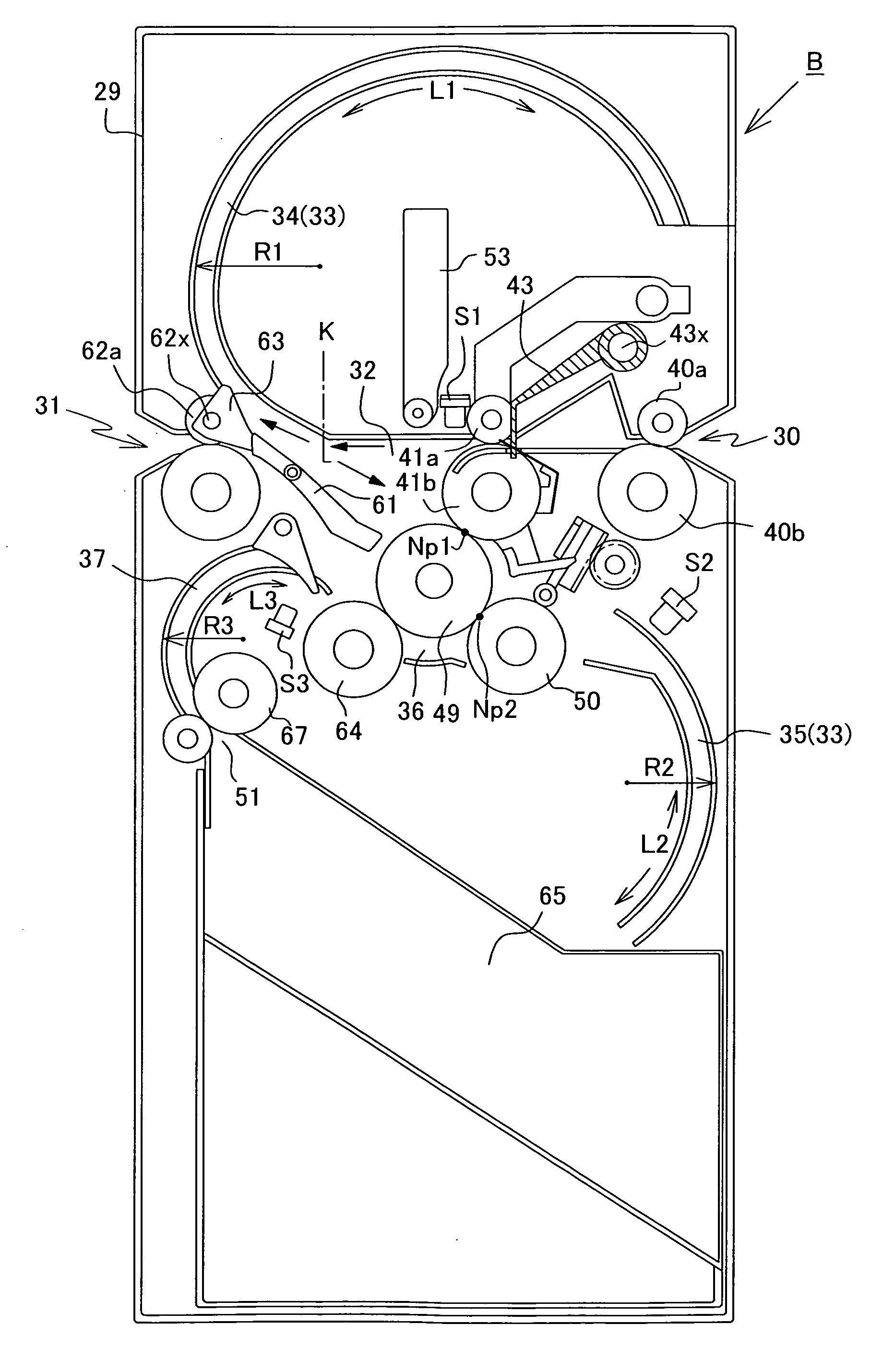
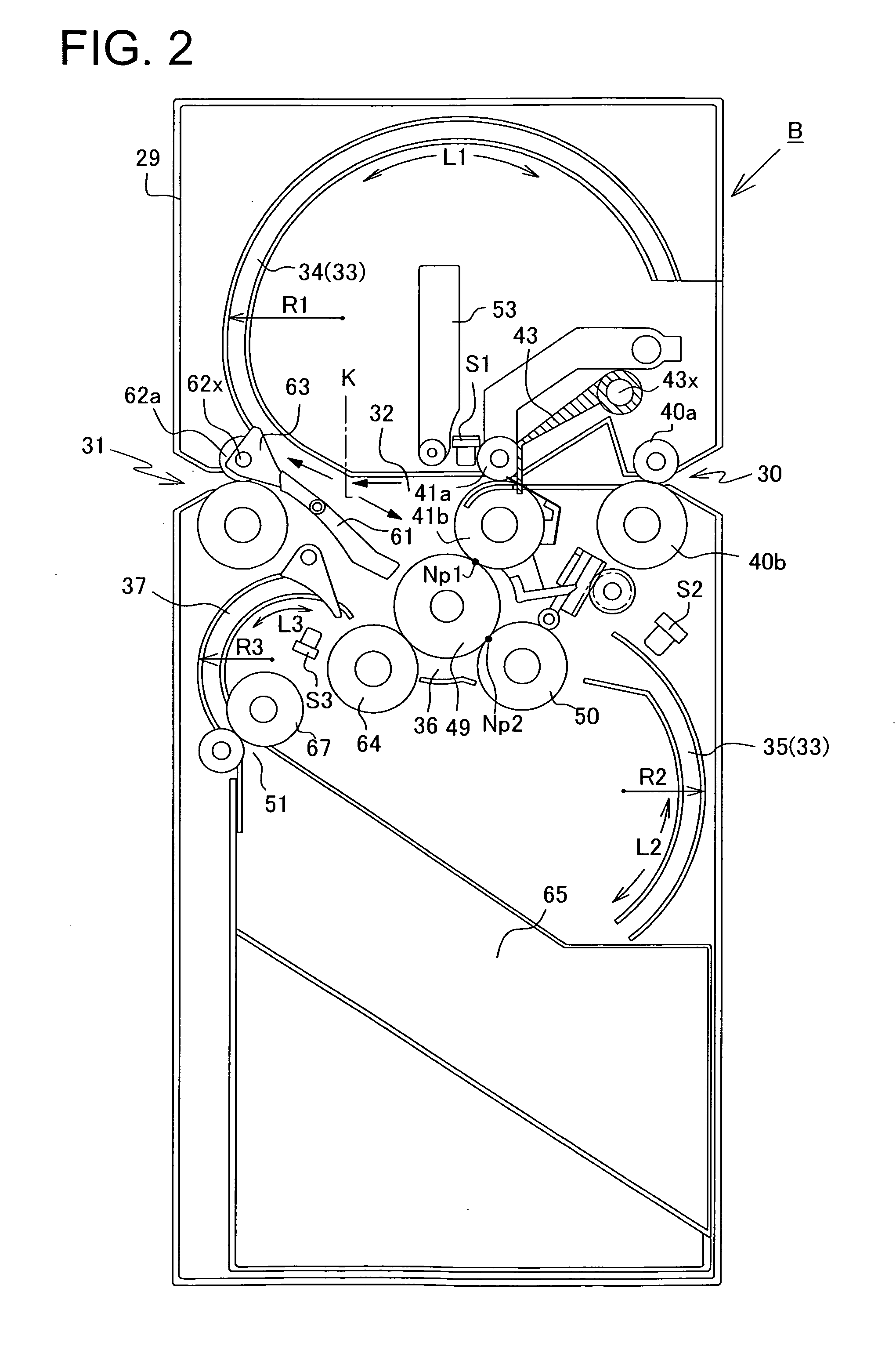
[0205]As a substitute for the folding deflecting members 53, 54 described based on FIG. 4, it is possible to configure the folding deflecting members to shift using cams as shown in FIG. 17.

[0206]As shown in FIG. 17, the sheet deflecting member 53, which guides (inserts) the fold position of the sheet to (in) the nip portion (first folding position) Np1, is provided with the driving means 85 for shifting the member 53 from the waiting position Wp (the solid-line position in FIG. 17) outside the path to the actuation position Ap (the dashed-line position) inside the path.

[0207]The above-mentioned folding deflecting member 53 is comprised of the driven roller 53a coming into contact with the roller periphery P2 of one of the folding roller pair, 41b, 49, and the up-and-down member 53c for holding at its one end the driven roller 53a to shift from the waiting position Wp to the actuation position Ap.

[0208]The up-and-down member 53c shown i...

embodiment 3

[Embodiment 3 of the Folding Deflecting Member]

[0231]FIGS. 20A and 20B show different Embodiments of the driving transfer member 86. In addition, the same configuration as in FIG, 17 is assigned the same reference numeral to omit the description thereof. The Embodiments shown in the figure illustrate the case where the driving transfer member 86 is comprised of a rotary cam.

[0232]First, in the Embodiment as shown in FIG. 20A, a rotary cam 87 is integrally attached to the driving rotary shaft 85x coupled to the shift motor MS. In the rotary cam 87 are formed a shift cam surface 87a in which a displacement amount increases at a constant rate (linearly) with respect to the displacement angle within the angle range θ1, and a non-shift cam surface 87b in which a displacement amount is zero with respect to the displacement angle within the angle range θ2.

[0233]Meanwhile, in the up-and-down member 53c, as in the member described previously, to the up-and-down member 53c are attached the dr...


PUM

PropertyMeasurementUnit
Shapeaaaaaaaaaa
Velocityaaaaaaaaaa

Abstract

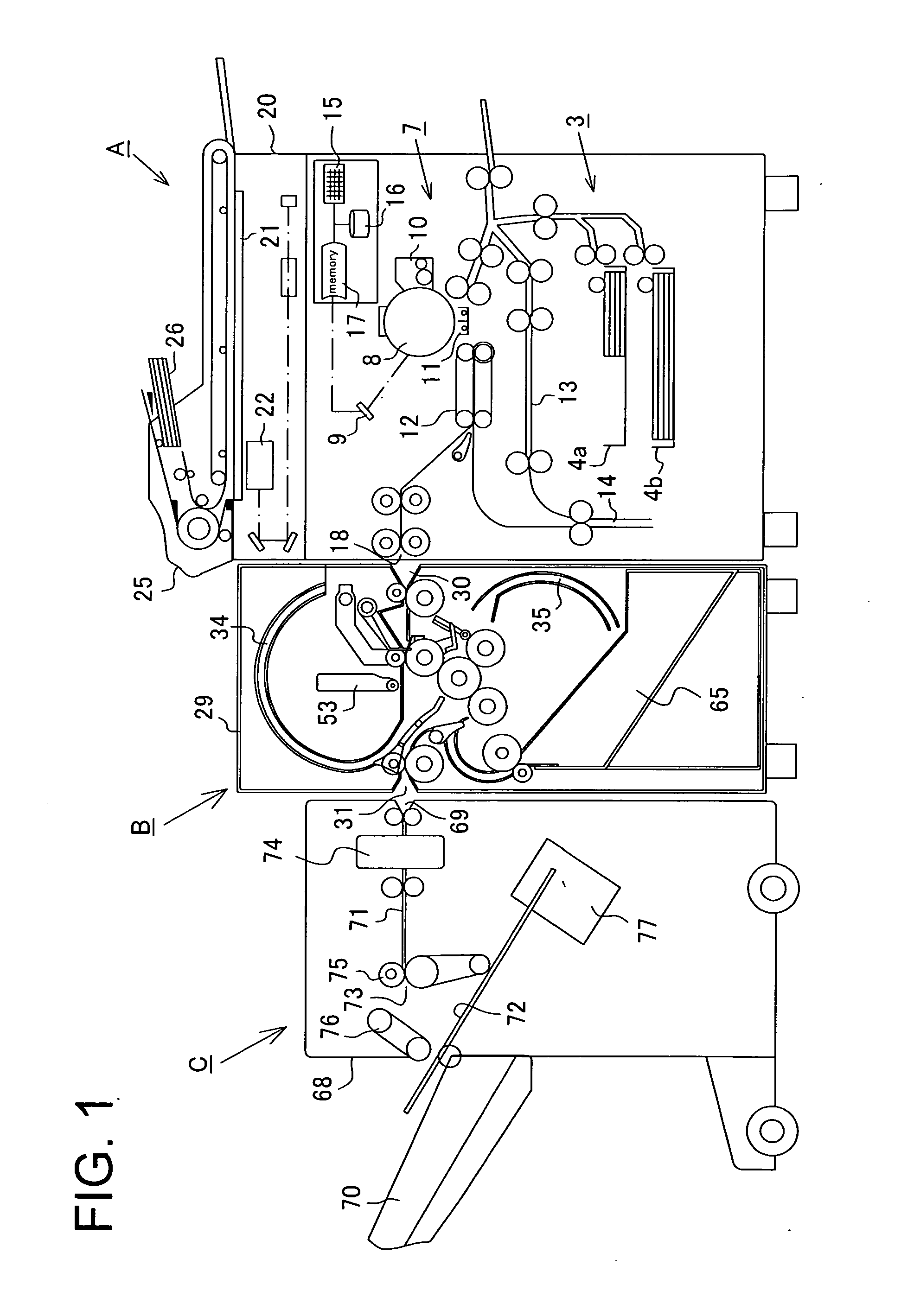
To enable a sheet to be folded in an accurate position with a simplified folding mechanism in performing folding processing on the sheet with a pair of folding rollers, a second transport path is disposed in a direction for crossing a first transport path for guiding a sheet from a carry-in portion to a carrying-out portion, and in the cross portion are disposed a folding roller pair for performing folding processing on a sheet, and a folding deflecting member for inserting a fold of the sheet in the nip portion. Then, the folding deflecting member is comprised of a driven roller that comes into press-contact with a roller periphery of the folding roller pair, and a shift member for shifting the driven roller from a waiting position to an actuation position, and by the operation of shifting the driven roller from the waiting position outside the path to the actuation position, the sheet front end portion is fed to the nip portion from an upstream-side guide path formed in the second transport path. At this point, the shift velocity of the driven roller is made higher than the velocity of the sheet sent from the first transport path.

Description

BACKGROUND OF THE INVENTION[0001]1. Technical Field[0002]The present invention relates to a sheet folding apparatus for folding a sheet with an image formed thereon, and more particularly, to improvements in the sheet folding mechanism for enabling a sheet to be folded in an accurate fold position with simplified structure.[0003]2. Description of the Related Art[0004]Generally, this type of sheet folding apparatus has been known as an apparatus for folding a sheet with an image formed thereon by an image formation apparatus such as a printing press, printer apparatus and copier in a predetermined fold position to perform finish processing. For example, Japanese Patent Application Publication No. 2008-247531 proposes an apparatus which is coupled to a sheet discharge outlet of an image formation apparatus, folds a sheet with an image formed for filing, and carries the sheet out to a subsequent binding processing apparatus.[0005]The sheet folding apparatus for thus folding a sheet in ...

Claims


Application Information

Patent Timeline
IPC IPC(8): B31B1/56B31B50/56
CPCB65H2801/27B65H45/12
Inventor SHIRAKURA, MIZUHOIMAZU, HIROKIITO, SHINICHIKAGAMI, TOSHIAKITOMONO, MITSUNORIKUBOTA, YUICHI
Owner NISCA KK
Learn More