
High intensity image projector using sectional mirror

a projector and sectional mirror technology, applied in the field of image projectors, can solve the problems of inefficient light from multiple lamps, and achieve the effects of high brightness, low power consumption, and increased light intensity

Active Publication Date: 2010-05-06
PROJECTIONDESIGN
View PDF5 Cites 6 Cited by
  • Summary
  • Abstract
  • Description
  • Claims
  • Application Information

AI Technical Summary

Benefits of technology

[0007]Embodiments of the present invention provide image projectors with increased light intensity (brightness) relative to known models using multiple light sources. For example, certain embodiments meet the needs for high brightness, while still providing any or all of compactness, low power consumption, and long lifetime. Regarding the increased brightness, embodiments of the present invention advantageously can produce flux levels that are 1.5 times or better than other known systems. This increase can reduce power consumption, material cost, and operating cost.

Problems solved by technology

However, these lamps combine light from the multiple lamps in an inefficient manner.

Method used


Image

  • High intensity image projector using sectional mirror
  • High intensity image projector using sectional mirror
  • High intensity image projector using sectional mirror

Examples


Embodiment Construction

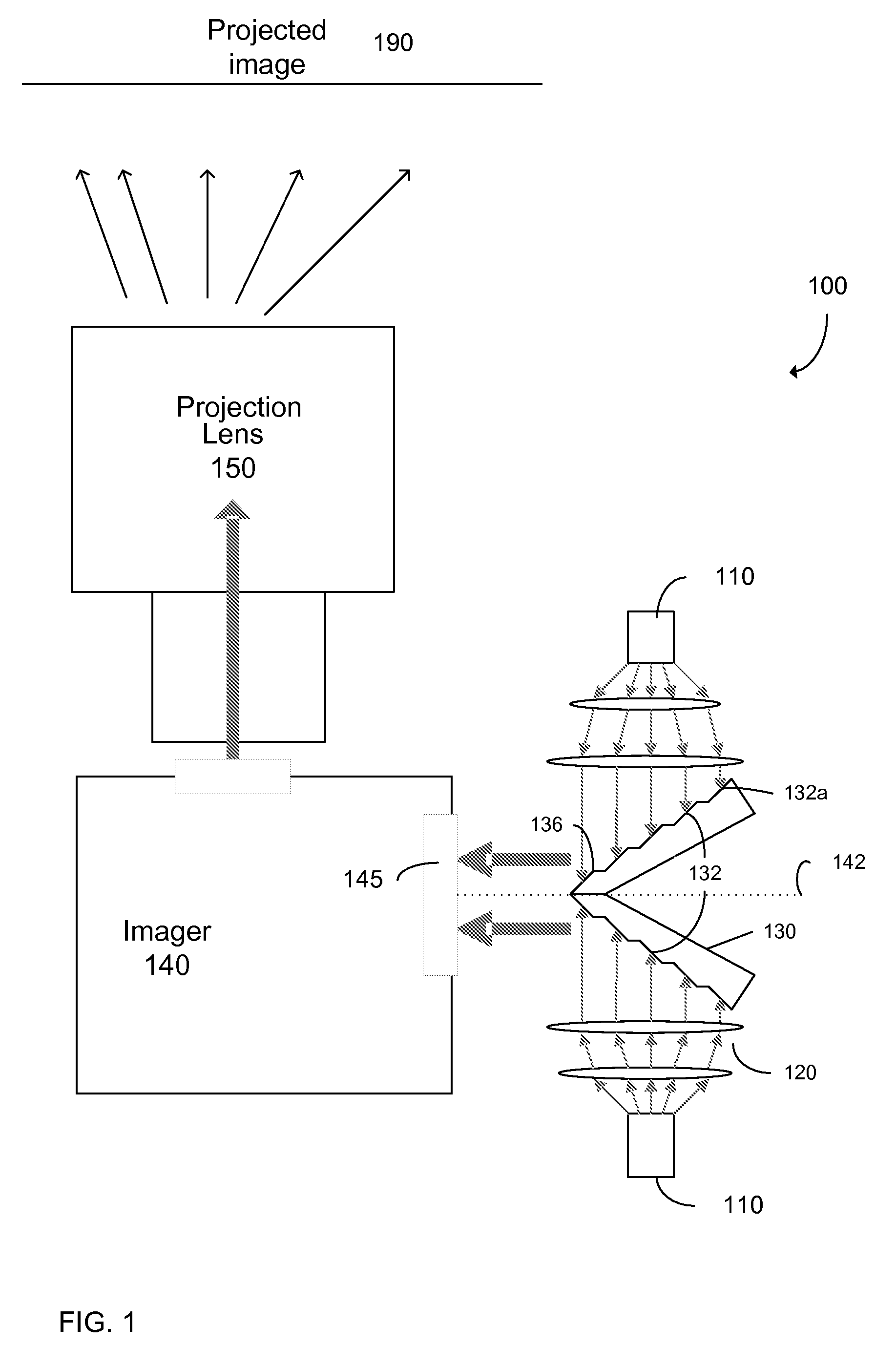
[0023]Embodiments of the present invention provide image projectors with increased light intensity (brightness) relative to known models using multiple light sources. To increase brightness, embodiments use mirrors to respectively compress the light from two light sources into a single pupil (e.g. an aperture) of an imaging device.

[0024]In one embodiment, the light from each light source creates a node intensity light pattern, which is focused on a respective stepped mirror. In one aspect, the light received at a stepped mirror has the same f-number as an entrance pupil of an imager. Each stepped mirror can compress its received light to 50% of the entrance pupil. The light reflected from the stepped mirror will transmit into the optical system and focused on the imager.

[0025]FIG. 1 is a schematic diagram of an image projector 100 according to an embodiment of the present invention. Light from sources 110 is used to create an image, which is then displayed as projected image 190. He...


PUM


Abstract

Image projectors with increased light intensity and methods for providing brighter images are provided. Image projectors, described herein, can provide the brightness while still providing any or all of compactness, low power consumption, and long lifetime. To increase brightness, sectional mirrors are used to respectively compress the light from two light sources into a single pupil (e.g. an aperture) of an imaging device. The compression can be accomplished by regions (e.g. sections) of the mirror having different angles with respect to the pupil. Relatively little light may be lost in the compression since minima for a light intensity pattern from a light source may occur between the regions that reflect the light.

Description

CROSS-REFERENCES TO RELATED APPLICATIONS[0001]This application is related to commonly owned U.S. Pat. No. 7,033,056 entitled “MULTI-LAMP ARRANGEMENT FOR OPTICAL SYSTEMS” by Odd Ragnar Andersen et al et al. (Attorney Docket No. 027467-000200US), filed May 2, 2003, the disclosure of which is incorporated by reference in its entirety.BACKGROUND[0002]The present invention relates to image projectors, and more specifically to image projectors having high intensity (brightness) and / or luminosity (total amount of light). Most projection systems today uses ultra high pressure (UHP) lamps, e.g. Mercury arc lamps, with wattage from 120 W-350 W and a lifetime of typical 1500-4000 h. These projectors are compact and portable with brightness level of typical 1000-5000 lumens. Most of these projectors are single lamp solutions. These arc lamp projectors are typically for home or office use where the space is relatively small.[0003]Projectors used for digital cinema, large venues, and for fixed in...

Claims


Application Information

Patent Timeline
IPC IPC(8): G03B21/28
CPCH04N9/3152H04N9/3164G03B21/2013G03B21/28G03B21/14H04N23/00
Inventor ANDERSEN, ODD RAGNAROLSEN, KJELL EINARLEFSAKER, SVERRE
Owner PROJECTIONDESIGN
Learn More