
Dynamic capacitor energy system

a capacitor energy system and dynamic capacitor technology, applied in secondary cells, capacitors with temperature varied dielectrics, instruments, etc., can solve the problems of high cost, large mounting structure, and inability to store energy in practical photovoltaic devices

Inactive Publication Date: 2010-05-06
PETERSON WILLIAM MEHRKAM
View PDF1 Cites 22 Cited by
  • Summary
  • Abstract
  • Description
  • Claims
  • Application Information

AI Technical Summary

Benefits of technology

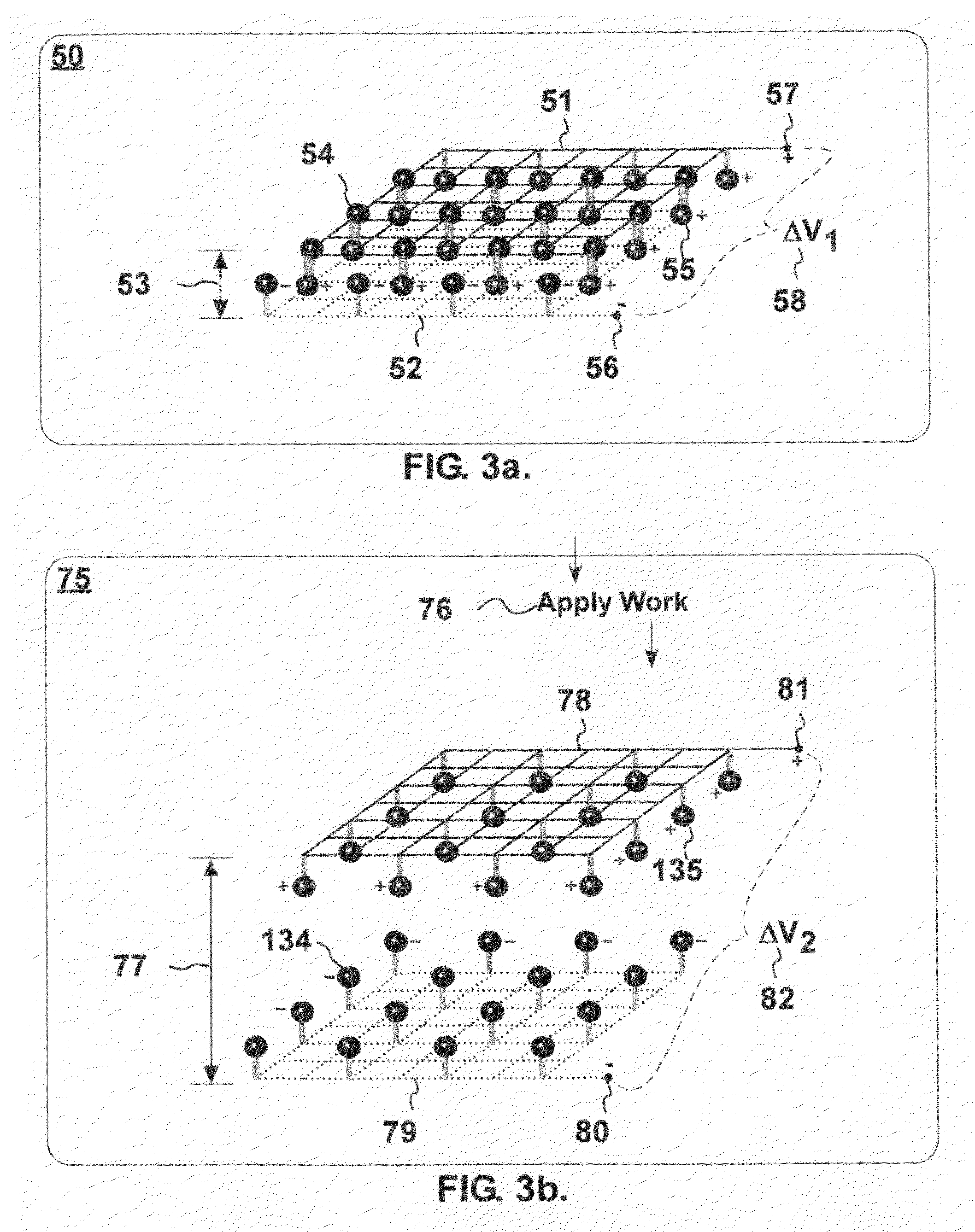
[0014]Another object of the present invention is to provide an energy system wherein a change in temperature can alter effective dielectric permittivity of variable capacitors thereby changing capacitance of the variable capacitor.

Problems solved by technology

However, all practical prior solutions have several major limitations.
For example, practical photovoltaic devices do not store energy (in themselves), are generally costly, must be customized for each installation, require delicate transparent enclosures and bulky mounting structures (usually on rooftops).

Method used


Image

  • Dynamic capacitor energy system
  • Dynamic capacitor energy system
  • Dynamic capacitor energy system

Examples


Embodiment Construction

[0080]In order to accurately and concisely describe the present invention, the following terms are first listed, then are defined below:

List of Defined Terms:

[0081]active relative motion configuration[0082]active relative motion configuration[0083]asphalt[0084]capacitance-controlling curve[0085]capacitance-controlling parameter[0086]charged particle[0087]conducted energy convection energy[0088]conducted energy modulator[0089]convection energy modulator[0090]core enclosure[0091]dc-to-ac inverter[0092]dielectric constant[0093]dual nested enclosure[0094]dynamic capacitor core[0095]dynamic capacitor energy system[0096]dynamic capacitor installation[0097]easy access enclosure[0098]electrode[0099]electrode shape[0100]encapsulant[0101]energy absorbing surface[0102]energy conversion cycle[0103]energy converting variable capacitor[0104]energy emitting surface[0105]energy redirector[0106]energy yield fraction[0107]explosion-damage limiting enclosure[0108]heat cell[0109]heat conveying device[0...


PUM

PropertyMeasurementUnit
angleaaaaaaaaaa
cycle timeaaaaaaaaaa
timeaaaaaaaaaa

Abstract

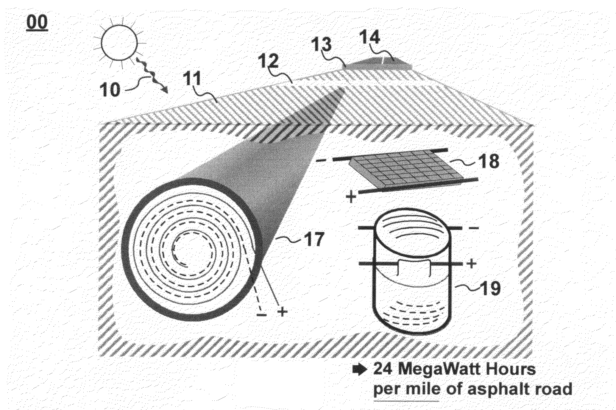
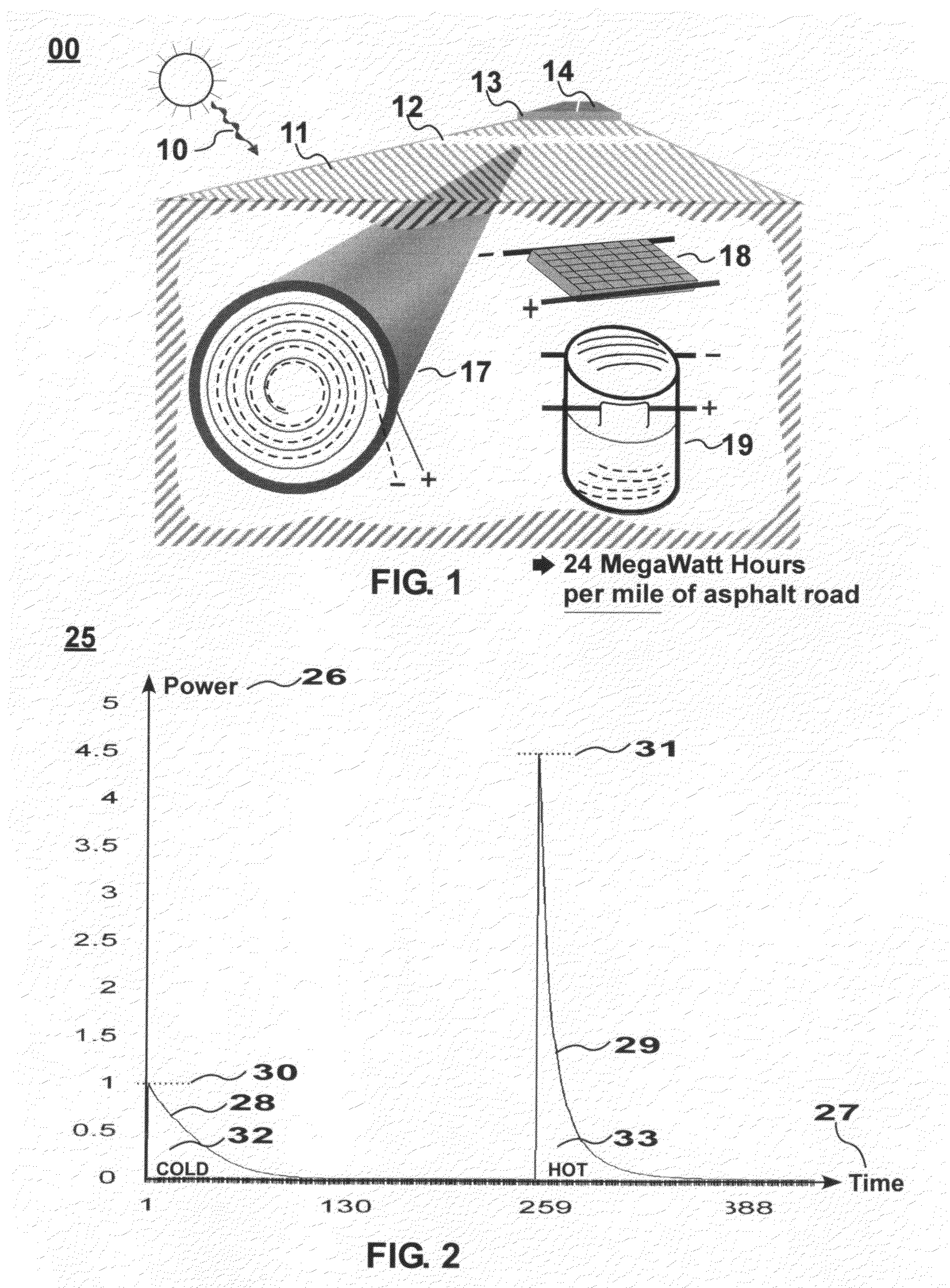
An energy conversion and storage system uses pre-charge-enabled energy-converting variable capacitors that can be buried in asphalt roads and streets. Radiant solar energy does work on temperature-sensitive capacitors. It modifies the capacitance of the previously cold and pre-charged capacitor, thereby converting solar energy into increased electrical energy available for practical commercial or residential use.

Description

BACKGROUND OF THE INVENTION[0001]People around the world are desperately seeking a breakthrough in sustainable, low-cost means for generating and storing electricity.[0002]Clean, sustainable energy sources like solar, tidal, and geothermal sources, can power the energy system of the present invention. Electricity is the optimum form of energy-output, due to its high transmission efficiency and ubiquitous use in homes, businesses and future automobiles. It is especially appropriate when combined with new high-energy storage capacitors, which are being co-developed and co-refined with the present invention.[0003]Truly global impacts from successful implementations of this invention can include the following: Virtual elimination of “oil addiction,” reversal of global warming and revitalization of global economies.[0004]The prior state of the technology includes ordinary means for photovoltaic and solar-thermal energy conversion. However, all practical prior solutions have several major...

Claims


Application Information

Patent Timeline
Patent Type & Authority Applications(United States)
IPC IPC(8): H02N11/00H01M10/44
CPCH01G7/04H02N11/002
Inventor PETERSON, WILLIAM MEHRKAM
Owner PETERSON WILLIAM MEHRKAM
Learn More