
Methods for optical identification and characterization of abnormal tissue and cells

a tissue and cell technology, applied in the direction of optical radiation measurement, diagnostics using spectroscopy, instruments, etc., can solve the problems of less sensitive, electrical impedance techniques, and relatively poor spatial resolution

Active Publication Date: 2010-04-29
LS BIOPATH
View PDF35 Cites 27 Cited by
  • Summary
  • Abstract
  • Description
  • Claims
  • Application Information

AI Technical Summary

Benefits of technology

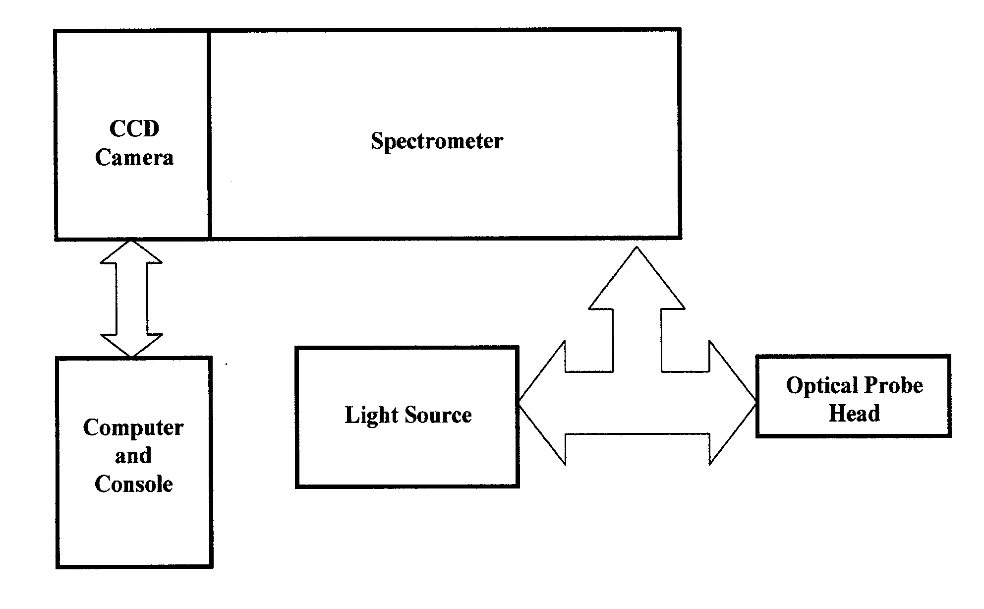
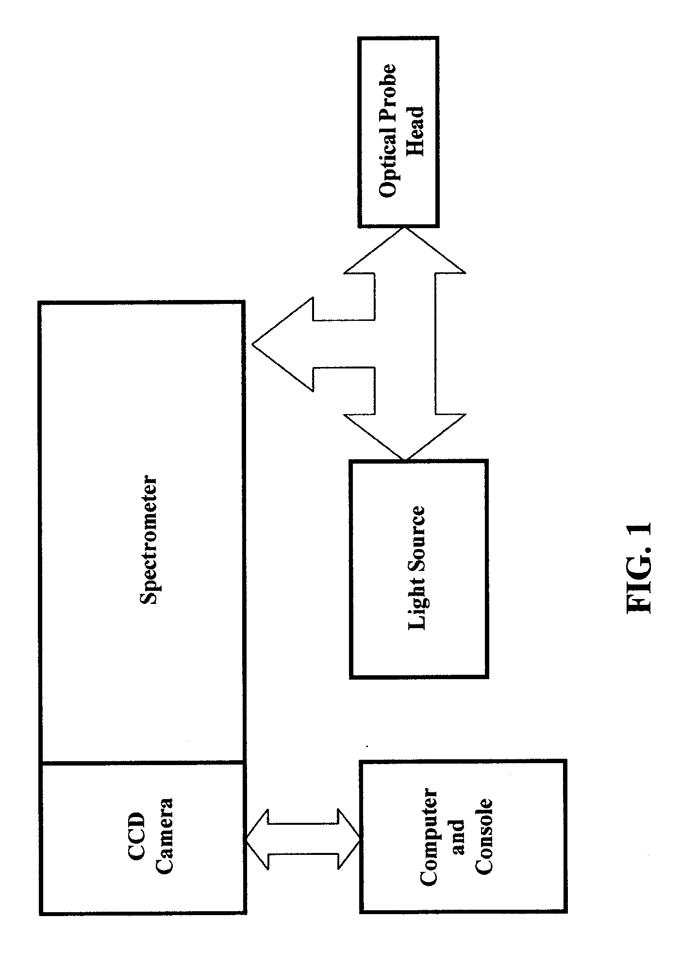
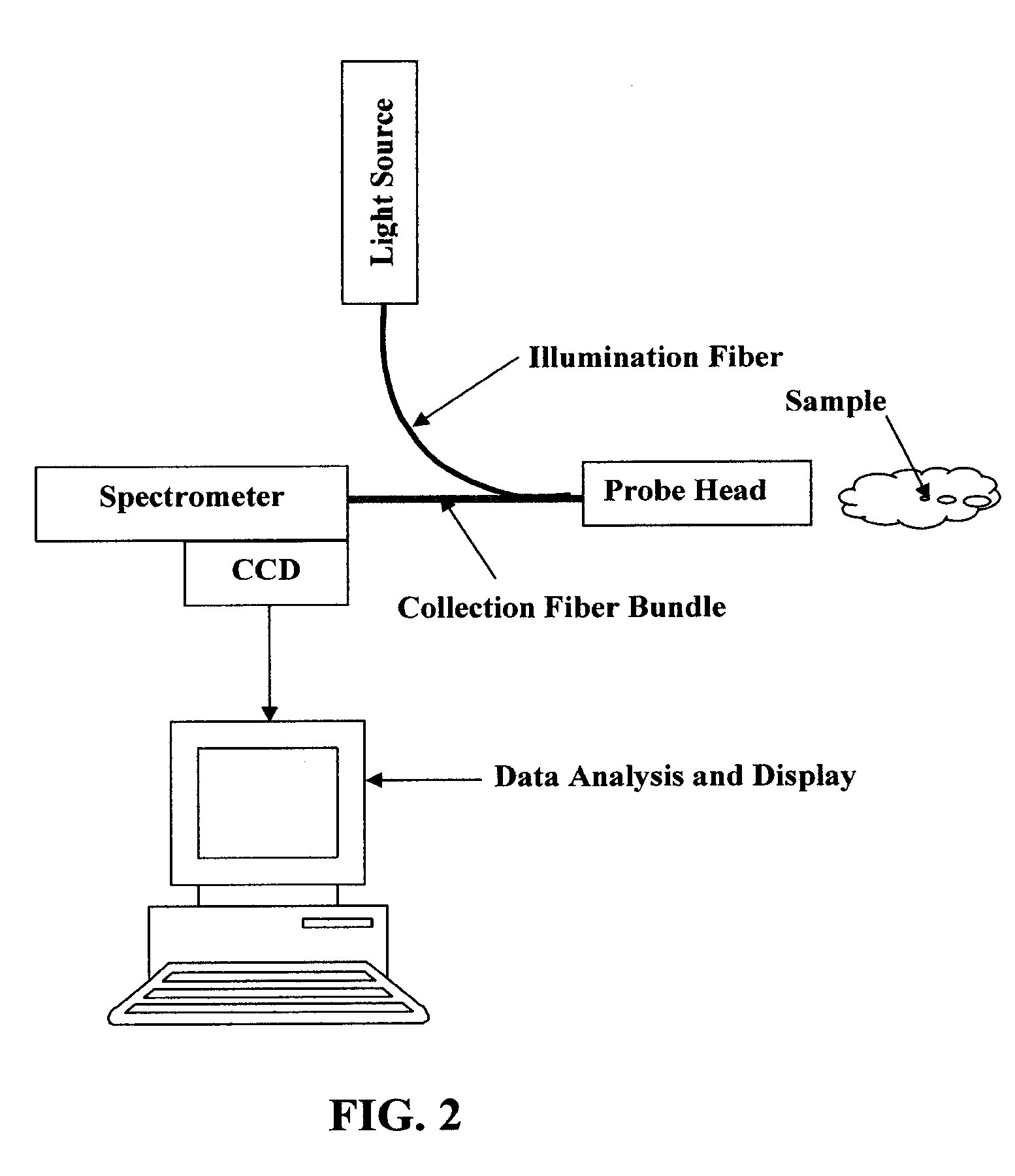
[0011]An aspect of the invention is directed to an apparatus for the diagnosis of a biological sample. The apparatus is comprised of an optical probe; a probe head distally connectable to the optical probe, the optical probe further comprising at least one optical element for applying an electromagnetic radiation of a first wavelength to the biological sample, and one or more collection elements positioned proximate the at least one optical element; and an analyzer for analyzing a signal received from the biological sample by the one or more collection elements. The probe head can be removable from the probe, if desired. Alternatively, the probe head can be integrally formed with the probe. In some configurations, the apparatus further comprises a plurality of serially deployable probe heads, each probe head comprising one or more optical elements, the one or more collection elements positioned proximate the one or more optical elements. The collection element of the apparatus can be comprised of an optical fiber with cladding. Additionally, the collection element can further comprise a spectral filter where the spectral filter is selected from the group comprising: an interference filter, low pass filter, high-pass filter, band pass filter, and Rayleigh filter. The optical element of the apparatus can be comprised of an optical fiber with a clad segment and a bare clad-less segment. The clad-less segment of the optical element can have conductive islands of film deposited on its surface. In some cases the apparatus has an optical element with a cross-section less than 500 microns. In some cases the optical element of the apparatus is less than 5 m in length. The optical element may further be adapted to be in communication with an exci...

Problems solved by technology

Electrical impedance techniques has the disadvantage that the detection of abnormalities in the tissues and the cells is done by measuring the changes in electrical impedance of the tissue globally rather than measuring electrical impedance locally because the current devices and methods are positioned outside of the body when in use.
Apparatuses that use global measures to detect changes in electrical impedance are less sensitive and have relatively poor spatial resolution.
Additionally, an X-rays machine cannot be used inside the body.
The use of ultrasound is further limited in the minimum size of detectable abnormal tissue because ultrasound imaging of smaller sizes is subject to poorer signal to noise ratio.
Similarly, it is also difficult to detect changes in cell density of the tissue in denser media.
Further, the MRI image is strongly affected by the amount of background noise from the overall tissue scanned and is also limited by the size of abnormal tissue that is detectable.
And like X-ray, MRI cannot be used inside of the body.
In the pathology lab, cancerous cells are characterized using histological methods which can be time consuming and may involve complex sample preparation procedures that can last anywhere from 8-12 hours.
Because the current techniques mentioned above are typically capable only of being positioned outside of the body there may be difficulty in detecting small volumes of abnormal tissue or testing small sample areas.
Also, positioning the detecting device outside of the body creates the potential for a greater amount of interference with neighboring tissue; makes it more difficult to reach the target tissue through structures in between the target tissue and the testing device; and increase the likelihood that the signal to noise ratio will be poor.
In addition, the current methods for detecting abnormal tissue employ bulky machinery.
Further, tissue samples are currently sent to pathology labs for testing which ultimately increases the time frame for making a diagnosis.
However, the technique works on thin tissue sections and requires the use of a microscopy set-up.

Method used


Image

  • Methods for optical identification and characterization of abnormal tissue and cells
  • Methods for optical identification and characterization of abnormal tissue and cells
  • Methods for optical identification and characterization of abnormal tissue and cells

Examples


example 1

Detection of Breast Cancer In Vitro

[0045]The optical device can be used to detect suspect areas of tissue during a lumpectomy. Once the surgeon excises the suspect breast tissue, either the surgeon, a pathologist, or lab technician in the operating room can use the handheld device as shown in FIG. 3 to investigate if the margins of the tissue are free of malignant tissue, the steps of which are shown in the FIG. 8. The user approaches the tissue with the handheld device and delivers electromagnetic radiation to the tissue at the desired location. The user than uses the device to detect and measure the electromagnetic radiation scattered by the suspected areas of tissue. A reference signal specific to the patient is collected from a clear benign portion of the tissue and the results of the benign tissue response are compared to the measurements obtained from the suspect portions of the sample. If it is determined that the suspect tissue is malignant tissue, the surgeon can follow up ...

example 3

Detection of Breast Cancer In Vivo

[0046]The optical device can also be used to detect cancerous tissue in vivo during a lumpectomy. During the lumpectomy, the surgeon will use the probe in the body cavity of the patient to assess if, once the suspect tissue has been excised, the remaining tissue in the breast is free of malignancy. Once the excision procedure is complete, the surgeon will use the device inside the body to scan the surface of the cavity. The results obtained from a benign tissue sample will be registered to form a baseline for the patient tissue response and the results from the suspect areas will be compared with the benign values. The console will display the variations in the tissue response. If the spectrum of scattered radiation from the sample varies from the spectrum from a benign sample, the surgeon will then note the area and will excise more tissue at the margins to ensure complete excision of the cancerous tissue before closing the patient.

example 4

Sentinel and Lymph Node Detection and Excision

[0047]As part of a typical cancer excision surgery the surgeons sometime excise sentinel lymph nodes and additional nodal areas to determine whether the cancer has metastasized. The optical probe can be used in vivo, to make sure that the node is cancer free before excising it. Additionally the device can be used in-vitro to find out if more lymph nodes need to be excised before the patient is closed.


PUM


Abstract

An optical system and apparatus for the diagnosis of a biological sample is disclosed. An embodiment of the apparatus includes an optical probe, a probe head distally connectable to the optical probe, the optical probe further comprising at least one optical element for applying an electromagnetic radiation of a first wavelength to the biological sample, and one or more collection elements positioned proximate the at least one optical element; and an analyzer for analyzing a signal received from the biological sample by the one or more collection elements.

Description

CROSS-REFERENCE[0001]This application claims is a continuation application of U.S. patent application Ser. No. 12 / 525,006 with an International Filing Date of Jan. 31, 2008, which claims the benefit of PCT / US2008 / 052608 filed on Jan. 31, 2008, under 35 USC §365, this application also claims the benefit of U.S. Provisional Application No. 60 / 898,683, filed Feb. 1, 2007, entitled “Optical System for Identification and Characterization of Cancer Cells” which application is incorporated herein by reference.BACKGROUND OF THE INVENTION[0002]The invention relates generally to diagnostic methods for real time diagnosis of biological cells and tissue. A diagnosis of abnormal tissue can be made by the detection of differences in properties of biological cells, properties such as cell density, size and composition. A diagnosis of abnormal tissue may also include a characterization of these differences in cellular properties. In addition to aiding a health care provider with making a diagnosis ...

Claims


Application Information

Patent Timeline
IPC IPC(8): A61B6/00
CPCA61B5/0075A61B5/0084G01N21/658A61B5/415A61B5/418A61B5/0091A61B2562/0233G01J3/0218G01J3/0291G01J3/44
Inventor SARFATY, MOSHELEV, AMIR
Owner LS BIOPATH
Learn More