
Semiconductor chip, method of manufacturing the semiconductor chip and semiconductor chip package

a semiconductor chip and semiconductor chip technology, applied in the field of semiconductor chip packaging, can solve the problems of insignificant shielding effect, unnecessary energy, and current flow to create electromagnetic noise, and achieve the effect of enhancing shielding

Inactive Publication Date: 2010-04-29
SAMSUNG ELECTRO MECHANICS CO LTD
View PDF4 Cites 23 Cited by
  • Summary
  • Abstract
  • Description
  • Claims
  • Application Information

AI Technical Summary

Benefits of technology

The present invention provides a semiconductor chip with a shielding layer that improves shielding effects and reduces the size of the chip package. The chip has electrode pads connected to an external ground through a conductive via. The chip is mounted on a substrate with a conductive film and bumps to connect the chip to the substrate. The conductive film is formed only on the chip's underside surface. The invention also provides a method for manufacturing the chip. The technical effects of the invention include improved shielding, reduced size, and improved grounding of the semiconductor chip.

Problems solved by technology

That is, regardless of the induction of the device, current flows to create electromagnetic noise, which is an unnecessary energy.
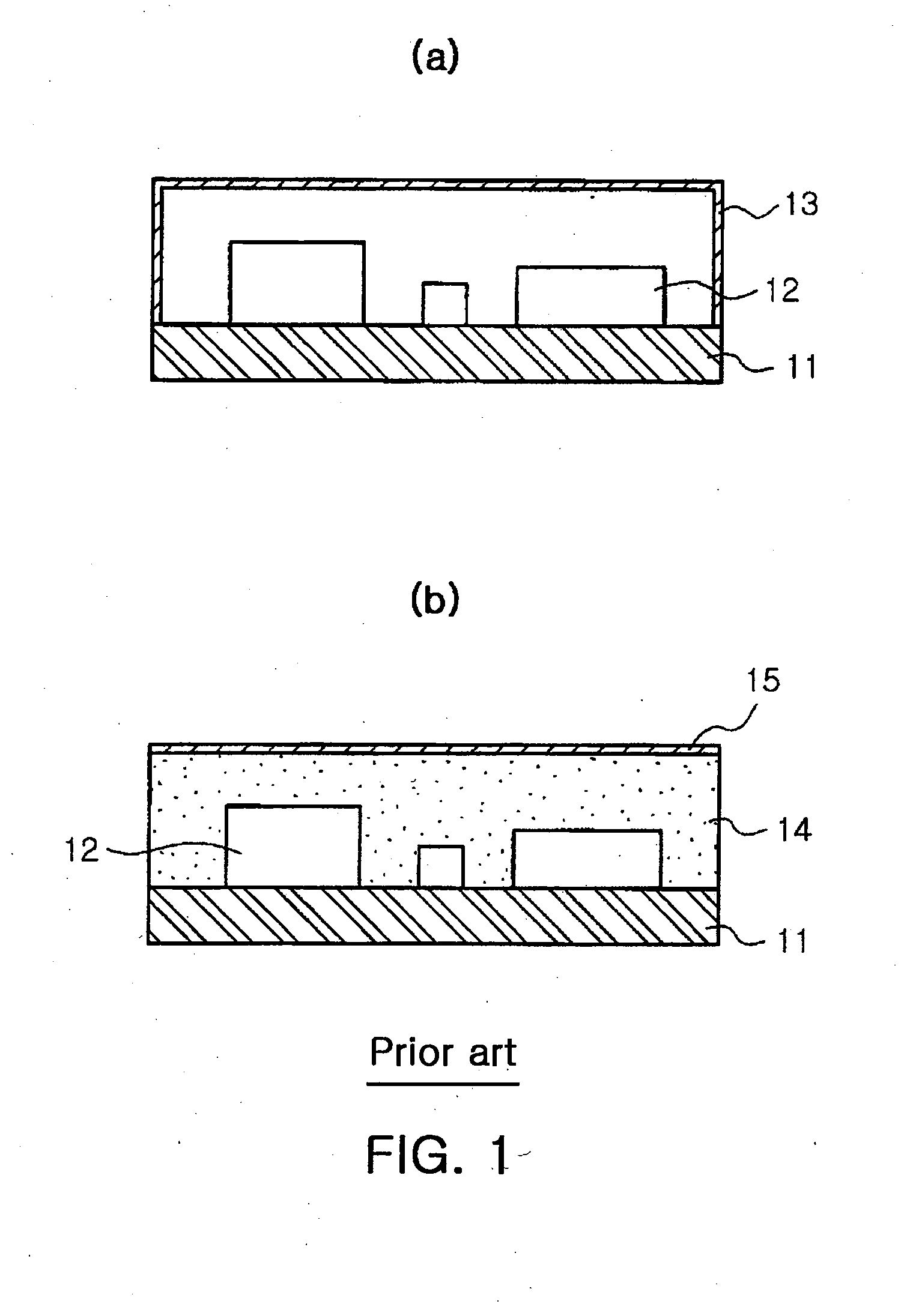
Such electromagnetic noise, if transferred to other devices through a path, leads to degradation in performance and malfunction thereof.
Yet, the metal film formed on the mold is not connected to a ground of the substrate, thus insignificant in terms of shielding effects.

Method used


Image

  • Semiconductor chip, method of manufacturing the semiconductor chip and semiconductor chip package
  • Semiconductor chip, method of manufacturing the semiconductor chip and semiconductor chip package
  • Semiconductor chip, method of manufacturing the semiconductor chip and semiconductor chip package

Examples


Embodiment Construction

[0034]Exemplary embodiments of the present invention will now be described in detail with reference to the accompanying drawings.

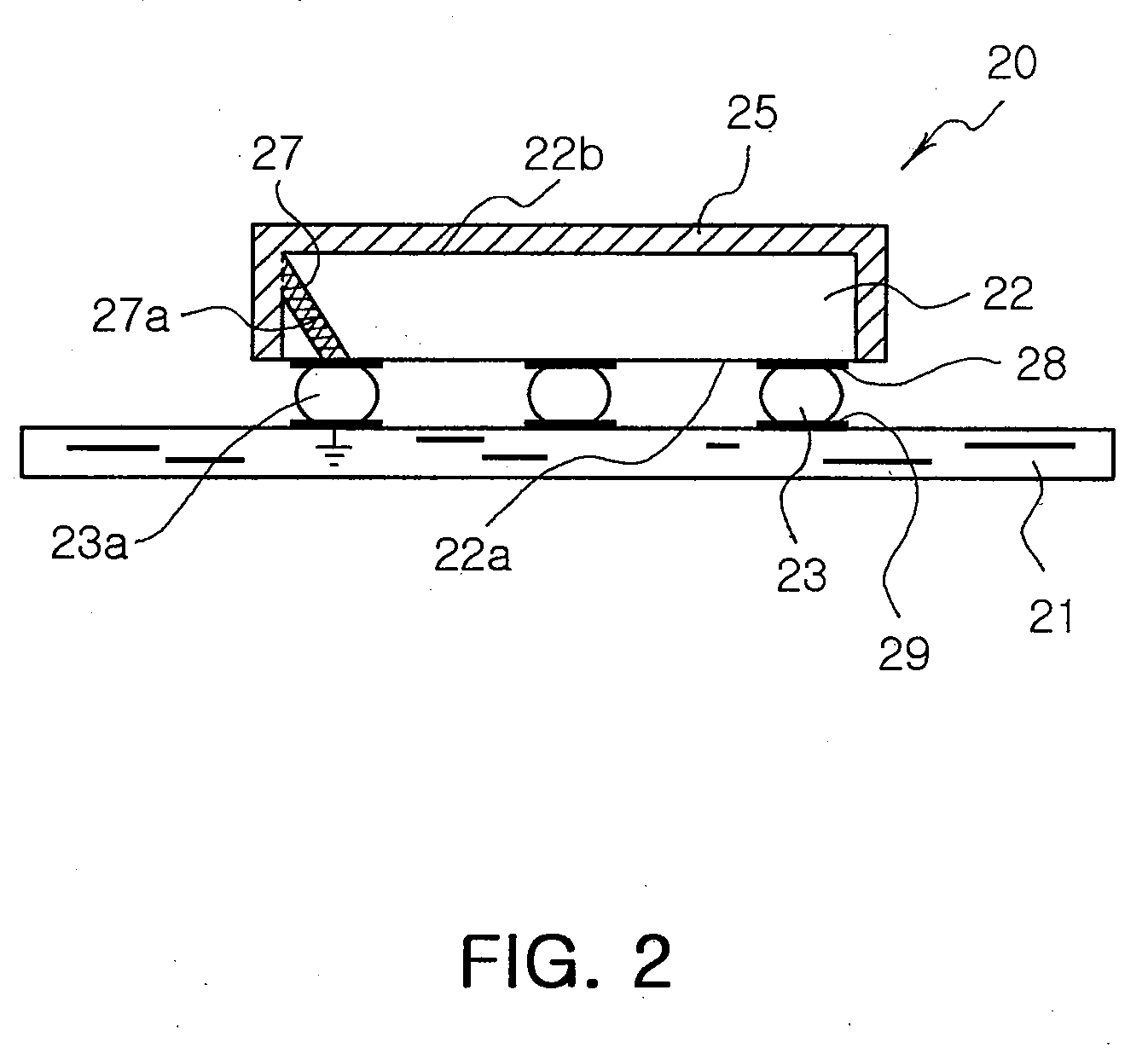
[0035]FIG. 2 is a cross-sectional view illustrating a semiconductor chip package having a semiconductor chip mounted on a substrate according to an embodiment of the invention.

[0036]Referring to FIG. 2, the semiconductor chip 20 is flip-bonded onto the substrate 21.

[0037]The semiconductor chip 20 has a body 22 provided with a plurality of electrode pads 28 on a top surface 22a thereof.

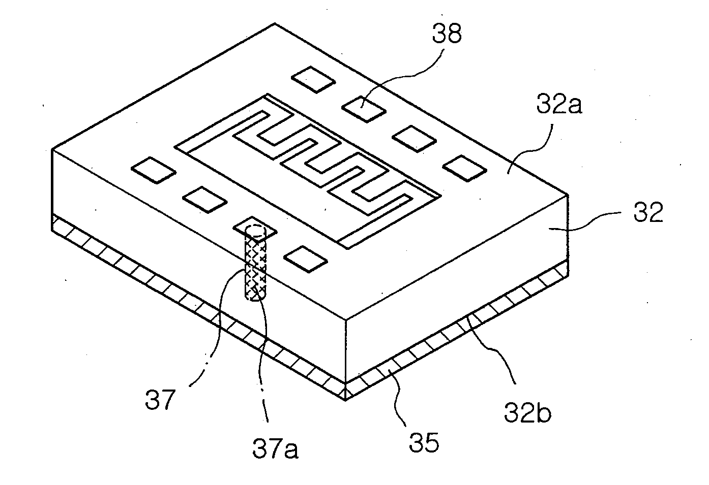
[0038]A conductive film 25 is formed on an underside surface 22b and side surfaces of the body 22 of the semiconductor chip where the electrode pads are not formed. Also, a via hole 27 is perforated through the top surface 22a and one of the side surfaces of the body 22.

[0039]The package substrate 21 is manufacturable by the same process as the one for fabricating a printed circuit board (PCB), or by High Temperature Chemical Cleaning (HTCC) or Low Temperature Co-fired Cerami...


PUM


Abstract

In a semiconductor chip, a body has a top surface where a pattern is formed, an underside surface opposing the top surface and a plurality of side surfaces. A plurality of electrode pads are formed on the top surface of the body to connect to an external terminal. A shielding conductive film is formed on the surfaces excluding the top surface of the body where the pattern is formed. A conductive via is extended through the body to connect one of the electrode pads with the conductive film.

Description

RELATED APPLICATIONS[0001]This application is a Divisional of U.S. Application Ser. No. 11 / 702,131, filed on Feb. 5, 2007, claiming priority of Korean Application No. 10-2006-0043946, filed on May 16, 2006, the entire contents of each of which are hereby incorporation by reference.BACKGROUND OF THE INVENTION[0002]1. Field of the Invention[0003]The present invention relates to a semiconductor chip package, more particularly, in which a shielding conductive film is connected to a ground through a via hole, and a manufacturing method thereof.[0004]2. Description of the Related Art[0005]A high frequency module for use in a mobile telecommunication device such as a mobile phone is constructed of a high frequency circuit including a high frequency semiconductor device and a periphery circuit that are formed on a substrate thereof.[0006]In general, current propagating in an electronic device induces electric field and magnetic field therearound, thereby generating a space due to electric p...

Claims


Application Information

Patent Timeline
Patent Type & Authority Applications(United States)
IPC IPC(8): H01L21/768H01L21/78
CPCH01L23/481H01L23/552H01L2224/13144H01L2224/13147H01L2224/16H01L2924/3025H01L2924/01078H01L2924/01079H01L2924/04941H01L2924/09701H01L2224/274H01L2224/0401H01L2224/0557H01L2224/16227H01L2224/05573H01L2224/05568H01L2224/05624H01L2224/05644H01L2224/05647H01L2224/0615H01L24/05H01L2924/00014H01L23/045
Inventor LEE, TAE SOOPARK, YUN HWI
Owner SAMSUNG ELECTRO MECHANICS CO LTD
Learn More