
Remote Optimizing Wireless Wan Modular Transmitter/Bridge

a wireless wide area network and modular technology, applied in the field of transmitters/bridges, can solve the problems of reducing the ability of the equipment to perform some of its functions, frustrating and potentially dangerous lost and interrupted communications, and incomplete transactions

Inactive Publication Date: 2010-04-29
ACCELERATED CONCEPTS
View PDF3 Cites 2 Cited by
  • Summary
  • Abstract
  • Description
  • Claims
  • Application Information

AI Technical Summary

Benefits of technology

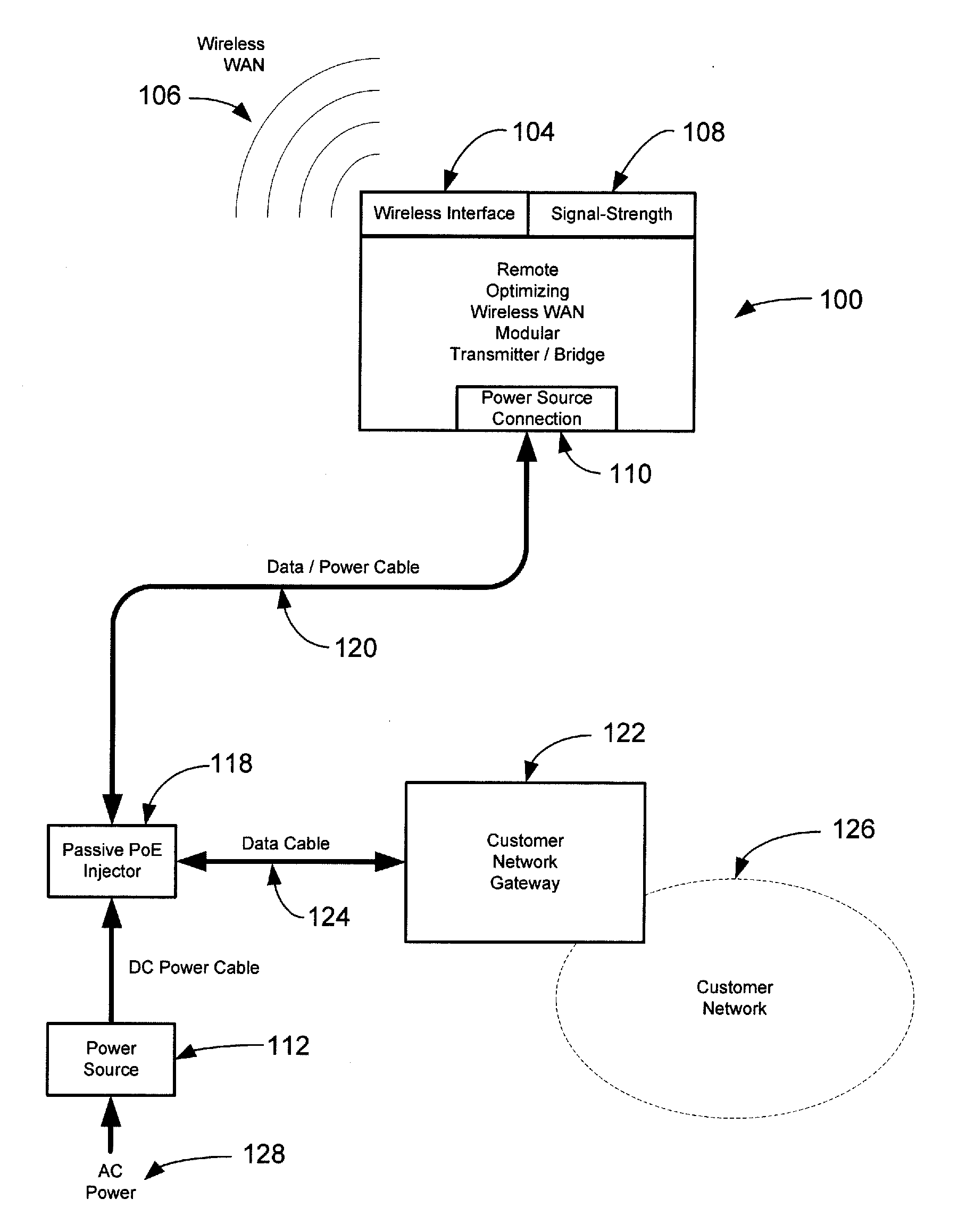
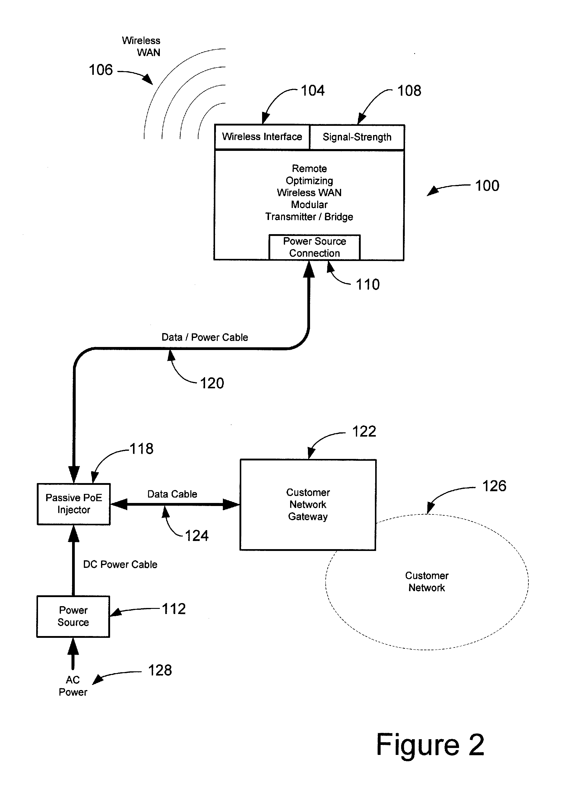
[0009]The invention is a modular optimizing transmitter / bridge, having a transmitter / bridge, a WWAN interface and a power connection. Remote power may be supplied using standard Power Over Ethernet (PoE) and / or Passive PoE or similar means. The device will be transparent to the end device and the wireless network. The device will also have a placement indicator to allow for optimal placement for maximum wireless connectivity.

Problems solved by technology

Therefore, the IT equipment is often surrounded with dense structures which reduce the ability of the IT equipment to perform some of its functions.
Lost and interrupted communications are frustrating and potentially dangerous when communications are disrupted.
Also, loss of business communications may result in incomplete transactions, loss of important business and financial data and similar problems.
Another problem with current IT equipment is that it is often difficult to determine an optimized location for a wireless transmitter.
Without a tool for detecting wireless transmissions and the strength of those transmissions, the user is forced to use a trial and error method of placing the transmitter in a location, testing the application, and then moving the transmitter to a new potential target location.
Furthermore, the individual or business may wish to have redundant communication lines, even while the IT equipment remain secure and surrounded by dense structures which can impede communications.

Method used


Image

  • Remote Optimizing Wireless Wan Modular Transmitter/Bridge
  • Remote Optimizing Wireless Wan Modular Transmitter/Bridge
  • Remote Optimizing Wireless Wan Modular Transmitter/Bridge

Examples


Embodiment Construction

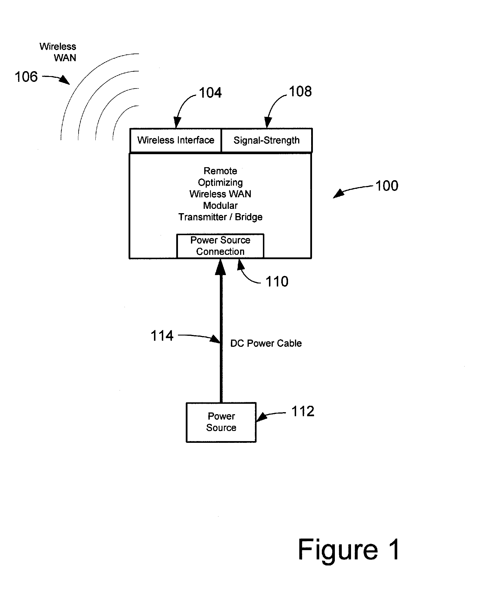
[0015]The present invention is an optimizing transmitter / bridge, shown generally in FIG. 1 at 100.

[0016]The optimizing transmitter / bridge 100 incorporates a transmitter / bridge 102. The transmitter / bridge 102 includes software for identifying signals from one or more WWAN service providers. The transmitter bridge may be one that has the functionality of routers such as those manufactured by NetGate, McAfee or Cisco. Furthermore, the transmitter / bridge may be incorporated within the functionality of a personal computer such as a PC.

[0017]The optimizing transmitter / bridge 100 also includes a WWAN Interface 104 for WWAN service 106 by a WWAN service provider. The WWAN Interface 104 may be internal or external to the optimizing transmitter / bridge 102, and typically consists of a 3G Wireless USB Modem. The WWAN interface 104 may include a modular slot so that the WWAN interface 104 of several WWAN service providers may be interchanged, so that the user may use the optimizing transmitter / b...


PUM


Abstract

The invention is a modular, optimizing transmitter / bridge device for optimizing placement of a transmitter / bridge for WWAN communication for one or more WWAN service providers, comprising a transmitter / bridge for WWAN communication, including software for identifying signals from the one or more WWAN service providers, a WWAN interface for providing WWAN service from a preselected WWAN service provider in electronic communication with the transmitter / bridge, a connection to a power source in electronic communication with the transmitter / bridge; and a signal strength indicator in electronic communication with the transmitter / bridge for indicating signal strength of a preselected WWAN service. The device will also have a signal strength indicator to allow for optimal placement for maximum wireless connectivity.

Description

CROSS-REFERENCE TO RELATED APPLICATION[0001]This application relates to the same subject matter as co-pending provisional patent application Ser. No. 61 / 107,790, filed by the same applicant on Oct. 23, 2008. This application claims the Oct. 23, 2008 filing date as to the common subject matter.BACKGROUND OF THE INVENTION[0002]1. Field of the Invention[0003]The disclosure relates generally to a transmitter / bridge. More particularly, the present invention relates to a remote optimizing wireless wide area network (WWAN) modular transmitter / bridge.[0004]2. Description of the Related Art[0005]Today most IT equipment is placed in a secure section of a building. The secure location is typically near the center of a building. Therefore, the IT equipment is often surrounded with dense structures which reduce the ability of the IT equipment to perform some of its functions. For example, the inherent properties of the dense structures at secure locations make them typically the least desirable ...

Claims


Application Information

Patent Timeline
IPC IPC(8): H04L12/26
CPCH04L12/10H04W88/08H04W84/105H04W24/02
Inventor NAGY, MICHAEL E.BUTTS, THOMAS A.
Owner ACCELERATED CONCEPTS
Learn More