Arrangement for detecting the change in a relative position of two parts in relation to one another

Inactive Publication Date: 2010-04-29
SIEMENS AG
View PDF10 Cites 0 Cited by
  • Summary
  • Abstract
  • Description
  • Claims
  • Application Information

AI Technical Summary

Benefits of technology

[0009]Hence the aim of the invention is to create a protection device which reliably registers the change in the relative position of two parts without using auxiliary energy, which is to a large extent forgery-proof and with which the information status can also be consulted remotely without a great deal of complexity and can also again be reset from there.
[0010]An object underlying the invention is to provide an arrangement by means of which the change in the relative position of two parts can to a large extent be detected in a forgery-proof manner, it being possible that the information status can be remotely monitored electrically and can again be reset after a change has taken place without auxiliary energy being necessary in situ and which is as economical as possible to manufacture.
[0019]The advantages mainly obtained with the invention are especially to be seen in the high security against forgery. Even if the mechanical registering device is opened by force, it is difficult to restore the ordering state of the monitoring bodies with a reasonable amount of effort. A further substantial advantage is to be seen in the non-destructive method of working. This makes it possible for the registering device to be reset again with ease by an authorized party, i.e. to be again made ready for use. The evaluation of the sensor signals can be carried out in a conventional manner via a digital circuit, such as for example a microprocessor. Manufacture is simple and requires comparatively few resources.

Problems solved by technology

If the seal was broken open and replaced by a forged one or if the seal broken open beforehand was re-sealed by skillful handling and the application of a suitable tool, this unauthorized access can however no longer be determined unequivocally.
The disadvantage is that the seal can be used only once.
A further disadvantage is that the seal is affixed from the outside, so that despite coding it is not to be excluded that the monitoring circuit is short-circuited from the outside prior to an improper access.
In this process, it should not be possible to identify the specific status of the seal so easily from the outside.

Method used


Image

  • Arrangement for detecting the change in a relative position of two parts in relation to one another
  • Arrangement for detecting the change in a relative position of two parts in relation to one another
  • Arrangement for detecting the change in a relative position of two parts in relation to one another

Examples


Embodiment Construction

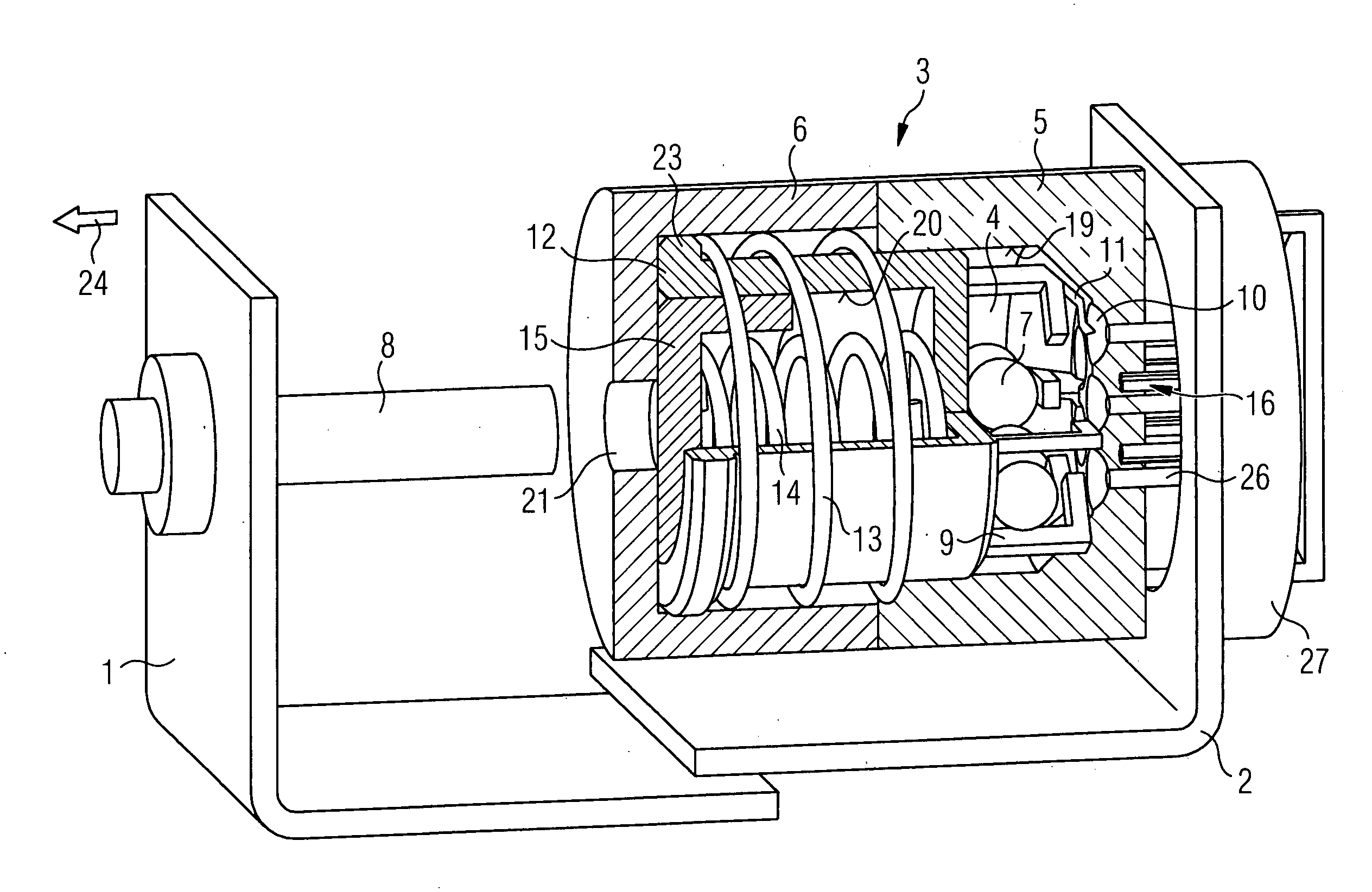
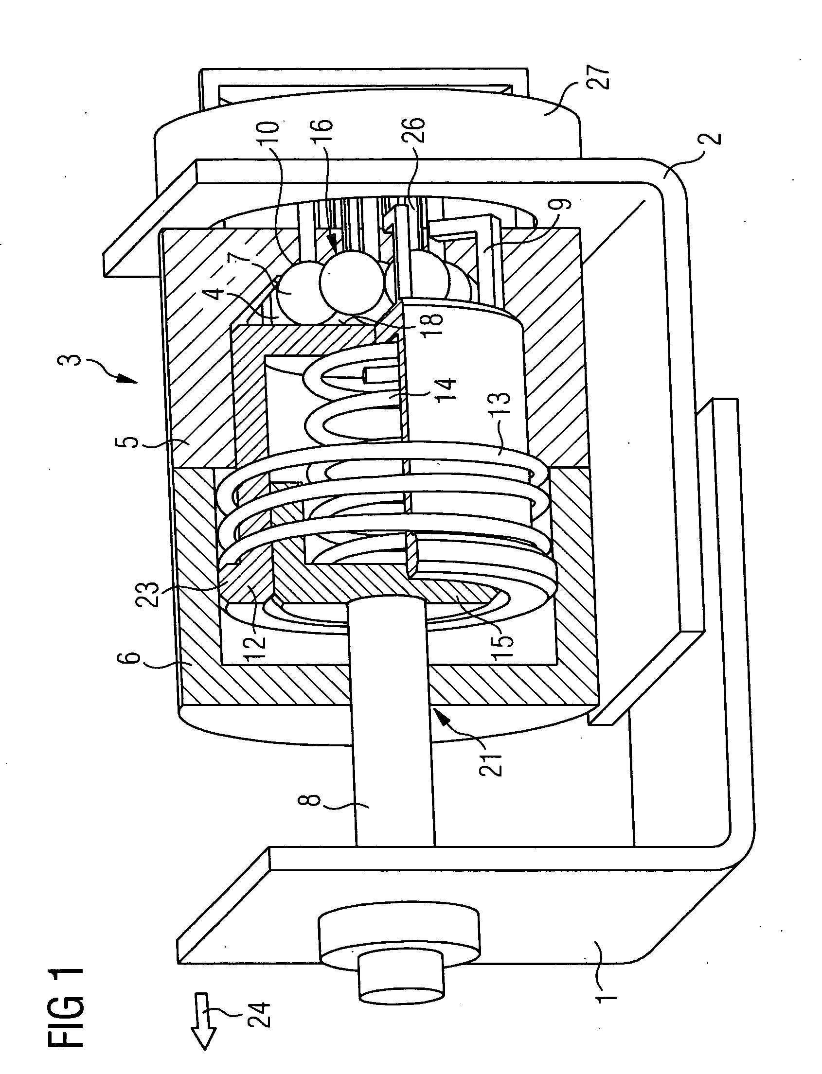
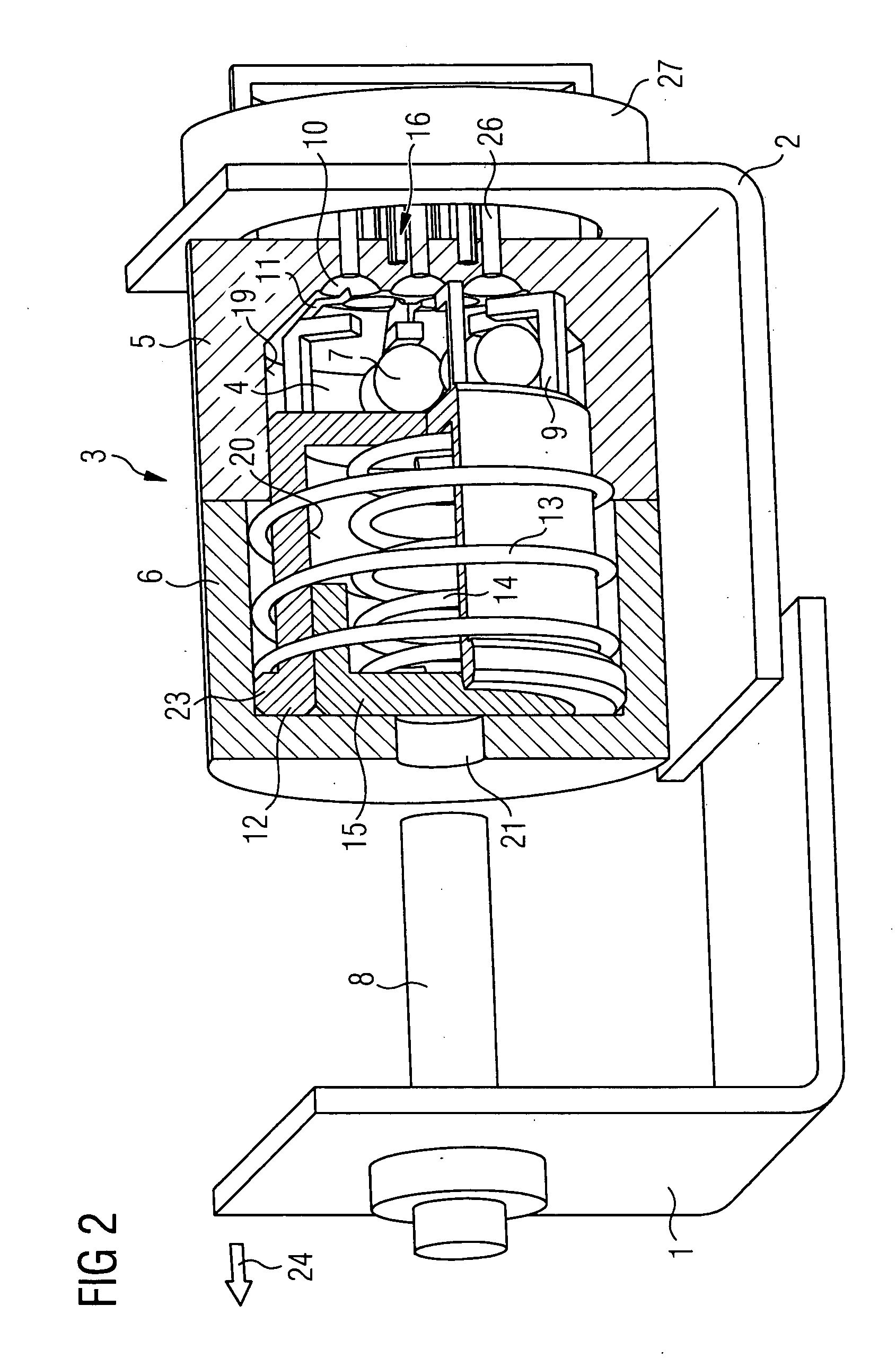
[0026]FIG. 1 shows a first exemplary embodiment of the invention and how it is for example used for registering an unauthorized opening of a casing of an electrical device. In FIG. 1 two parts which can be displaced in relation to one another are referred to with the reference symbol 1 and 2 and are connected to the parts of a casing not represented in detail (e.g. casing door and chassis) of an electrical device to be monitored. The reference symbol 3 refers to an entire electromechanical registering device. The registering device 3 consists of a monitoring chamber 4, a number of monitoring bodies 7, a sensor device 16 and motion transfer means described in more detail below, which transfer a change in the position of parts 1, 2 in relation to one another to the arrangement of the monitoring bodies 7 in the monitoring chamber 4. In the illustrated exemplary embodiment, the monitoring chamber 4 is formed by a first and a second annular cylinder 5, 12. Each of the annular cylinders 5...


PUM


Abstract

There is described an arrangement for detecting a change in a position between two parts which can be displaced in relation to one another. The arrangement has at least one electromechanical registering device having a monitoring chamber, which is shielded from manipulations taking effect from the outside, a number of monitoring bodies in the monitoring chamber, the number comprising at least two components and these components differing from one another in terms of a physical parameter, motion transfer means, which, in the event of the change in the positioning being returned to an initial state, cause the monitoring bodies to be moved from a first monitoring arrangement into a second monitoring arrangement. A sensor device has sensors which generate a sensor signal corresponding to the physical parameter of a monitoring body associated with each sensor in the first and second monitoring arrangement, and each sensor signal is fed to an evaluation unit.

Description

CROSS REFERENCE TO RELATED APPLICATIONS[0001]This application is the US National Stage of International Application No. PCT / EP2006 / 061685, filed Apr. 20, 2006 and claims the benefit thereof. The International Application claims the benefits of German application No. 10 2005 028 183.4 DE filed Jun. 17, 2005, both of the applications are incorporated by reference herein in their entirety.FIELD OF INVENTION[0002]The invention relates to an arrangement for detecting the change in the positioning between two parts which can be displaced in relation to one another.BACKGROUND OF INVENTION[0003]It is generally known that measuring devices which register energy consumption, such as for example electricity meters, water meters or gas meters, are secured by means of metal seals. Also security transport containers, containers and areas to which unauthorized persons have no access are sealed by means of metal seals or other seals, for example self-adhesive seal labels known as “VOID Labels”. A m...

Claims


Application Information

Patent Timeline
IPC IPC(8): G01B7/14G01R27/08G01B11/14H03M1/22
CPCG01R11/24
Inventor SIEBOLD, CARSTEN
Owner SIEMENS AG
Why Eureka
Try Eureka