
Rear door structure

a rear door and structure technology, applied in the direction of doors, roofs, transportation and packaging, etc., can solve the problems of increasing costs, and achieve the effect of improving rigidity and good balance of the lateral beam

Active Publication Date: 2010-04-29
HONDA MOTOR CO LTD
View PDF15 Cites 15 Cited by
  • Summary
  • Abstract
  • Description
  • Claims
  • Application Information

AI Technical Summary

Benefits of technology

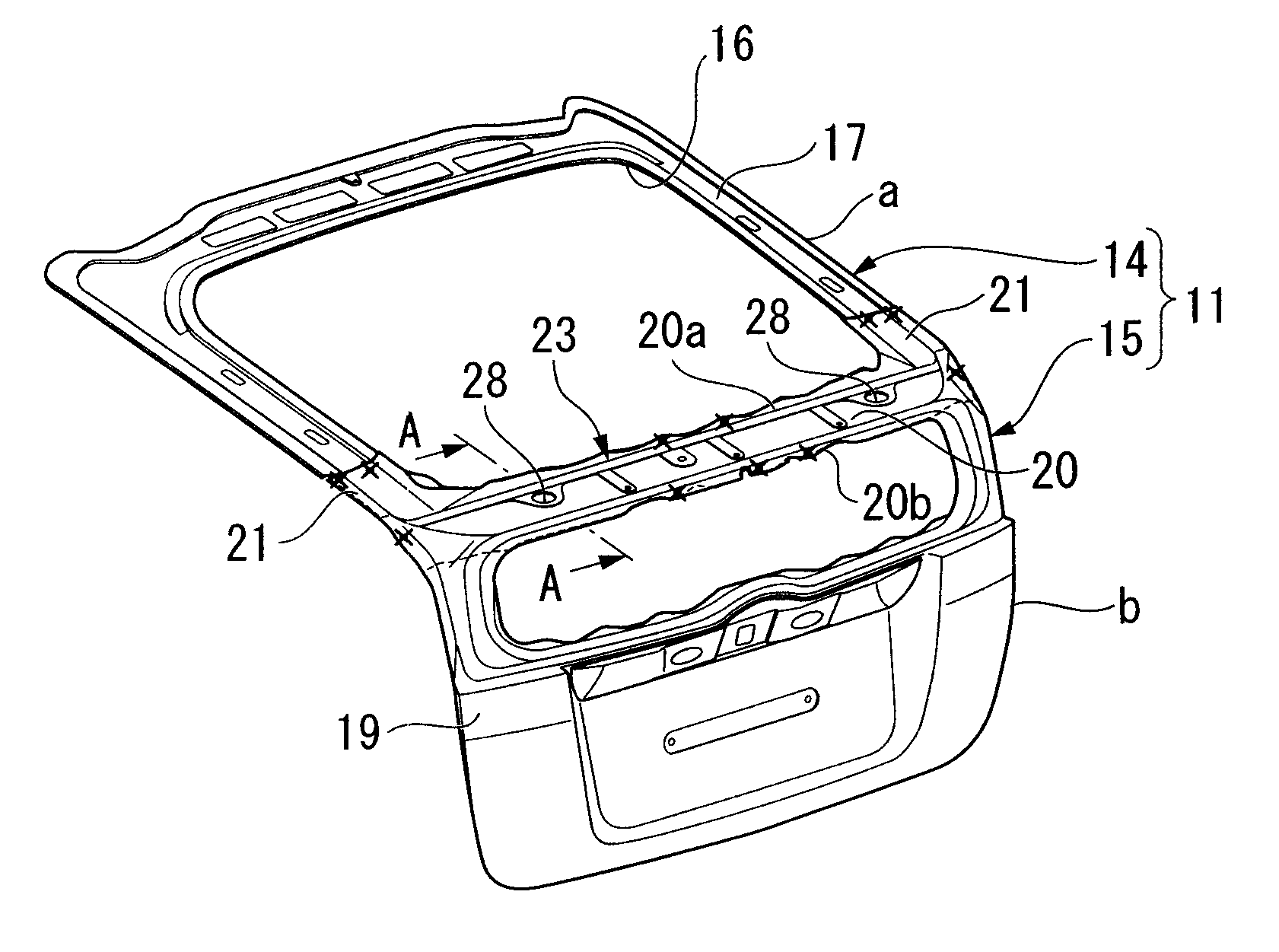
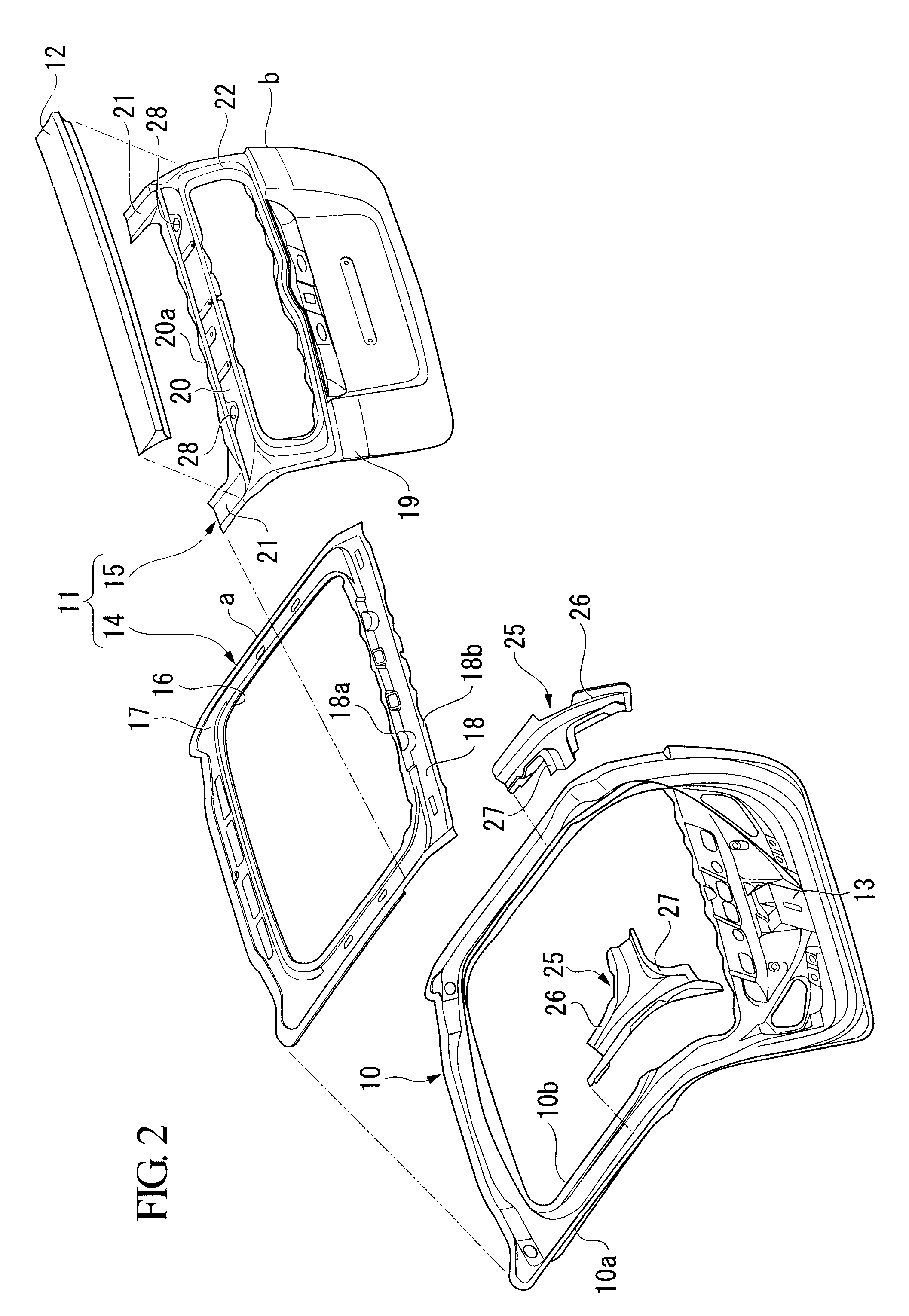
[0013]Specifically, since the door panel is reinforced in the vehicle width direction with the lateral beam having a closed sectional structure formed by overlapping the upper door panel and the lower door panel, it is possible to enhance the rigidity of the rear door structure which is simplified without increasing the number of parts.
[0015]In this case, because of the presence of the extending portions formed on the lower door panel, the lower corner portions of the frame portion are reinforced and the upper door panel and the lower door panel are solidly joined to each other. Specifically, the extending portion, which is provided at each lateral end of the upper edge portion of the lower door panel so as to extend upward, overlaps and is joined to both lateral side portions of the frame portion. As a result, because of the presence of the extending portions formed on the lower door panel, the lower corner portions of the frame portion are reinforced to enhance the rigidity of the frame portion in clamping the rear glass, and the upper door panel and the lower door panel are solidly joined to each other.
[0016]It may be arranged that the above-described rear door structure further includes a reinforcing member which extends over the lateral beam and both lateral edges of the upper door panel and the lower door panel. In this case, since there is provided the reinforcing member which extends over the lateral beam and both Lateral edges of the upper door panel and the lower door panel, the rigidity of both ends of the lateral beam can be reliably enhanced.
[0019]Therefore, since the reinforcing members are joined to the door frame, a load applied to the lateral beam can also be borne by the door frame, and thereby the support stiffness of both ends of the lateral beam can be further enhanced.
[0022]Specifically, the welding gun can be inserted into the welding work hole formed on one of the lower door panel and the upper door panel in the beam forming region, and thus the tip of the welding gun can be pressed onto the coupling portion of the reinforcing member and the other of the lower door panel and the upper door panel. As a result, welding work between the other of the lower door panel and the upper door panel and the reinforcing member can be performed reliably and easily in the closed cross section of the lateral beam.
[0024]In this case, since the lower door panel and the upper door panel are mutually spot welded at the center and both ends, with respect to the vehicle width direction, of the beam forming region forming the lateral beam, the rigidity of the lateral beam can be enhanced over the entire length thereof with good balance.

Problems solved by technology

Thus, there is a concern that as the number of parts increases, the cost increases.

Method used


Image

  • Rear door structure
  • Rear door structure
  • Rear door structure

Examples


Embodiment Construction

[0030]An embodiment of the present invention will be explained below with reference to the drawings. In the following explanation, unless otherwise specified, “top”, “bottom”, “left”, and “right” refer to the top, bottom, left, and right with respect to the vehicle body.

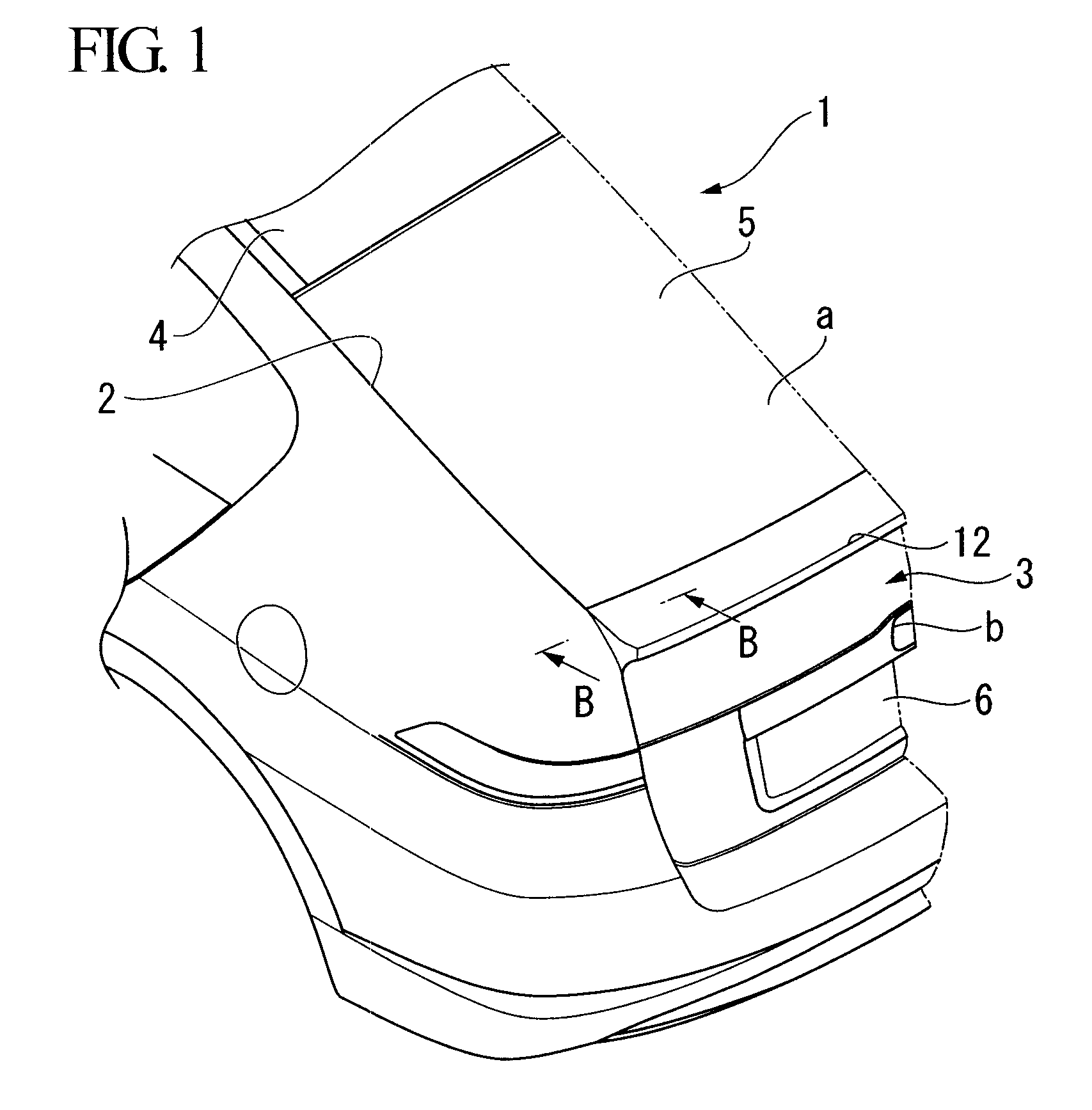
[0031]FIG. 1 shows a vehicle 1 employing a rear door structure according to the embodiment of the present invention.

[0032]As shown in the figure, the vehicle 1 is a hatchback type vehicle in which a surface of the rear portion of the vehicle body thereof is provided with an opening portion 2 on which a rear door 3 is openably and closably provided. The upper end of the rear door 3 is supported at the upper edge of the opening portion 2 so that the rear door 3 can be flipped up. The rear door 3 includes an inclined surface a and a vertical surface b, the inclined surface a, when the rear door 3 closes, inclining backward and downward from a roof 4 of the vehicle body and the vertical surface b, when the rear door 3 cl...


PUM


Abstract

A rear door structure in which a rear door is openably and closably provided on a rear portion of a vehicle body, including a door panel, wherein: the door panel includes an upper door panel and a lower door panel provided on the lower portion of the upper door panel; and a lower edge portion of the upper door panel and an upper edge portion of the lower door panel mutually overlap so as to form a lateral beam having a closed cross section and extending in a vehicle width direction.

Description

[0001]Priority is claimed on Japanese Patent Application No. 2008-273162, filed Oct. 23, 2008, the contents of which are incorporated herein by reference.BACKGROUND OF THE INVENTION[0002]1. Field of the Invention[0003]The present invention relates to a structure of a rear door openably and closably provided at a rear opening portion of a vehicle.[0004]2. Description of the Related Art[0005]In hatchback type vehicles or the like, an opening portion is provided at a rear portion of a vehicle body, at which a rear door is openably and closably provided. The rear door is generally provided with a frame portion to which a rear glass is attached.[0006]There is known a vehicle rear body structure having the above-described structure at a rear portion of a vehicle body, in which a lateral beam having a closed sectional structure is provided so as to extend along a lower edge of a rear glass (see, for example, Japanese Unexamined Patent Application, First Publication No. 2007-176358).[0007]I...

Claims


Application Information

Patent Timeline
IPC IPC(8): B60J5/10
CPCB60J5/107B60J5/101
Inventor MIYAKE, YOSHINORIMUNENAGA, KENICHI
Owner HONDA MOTOR CO LTD
Learn More