
Iliac leg extension stent graft

a technology of iliac leg and stent, applied in the field of medical devices, can solve the problems of stent graft and blood flow restriction, and achieve the effect of reducing the potential for either of these kinking problems

Active Publication Date: 2010-04-22
THE CLEVELAND CLINIC FOUND +1
View PDF22 Cites 26 Cited by
  • Summary
  • Abstract
  • Description
  • Claims
  • Application Information

AI Technical Summary

Benefits of technology

[0004]The present invention seeks to provide a stent graft in which the potential for either of these kinking problems can be reduced or at least provide the physician with a useful alternative device.
[0008]The preferred embodiment provides a leg extension stent graft device with a flexible uncovered self-expanding stent tail which can assist with controlling convolutions along the length of the iliac artery. The uncovered stent portion of the leg extension can assist in preventing any convolutions in the artery from forming kinks in the covered tubular body portion of the leg extension. The uncovered section can bend to take up any convolution without kinking whereas the same amount of bending in a covered tubular body could cause kinking.
[0009]In one embodiment, the uncovered tubular self-expanding stent assembly comprises a plurality of zig-zag self-expanding stents flexibly linked together. The flexible linking together can be by use of a suture thread tied to alternate apices of adjacent zig-zag stents to provide a degree of flexibility between adjacent stents.
[0012]Preferably, a second end of the tubular body opposite to the first end is provided with an outside sealing surface and at least one self-expanding stent within the tubular body at the second end, in order to assist with sealing of the leg extension device into one of the legs of a bifurcated stent graft deployed into the aortic bifurcation.
[0014]The uncovered tubular self-expanding stent assembly can extend within the tubular body for a distance equivalent to at least the diameter of the tubular body, in order to assist with providing a stable transition from the covered body portion to the uncovered portion.

Problems solved by technology

There can be problems with such stent grafts, however, for example in cases in which the iliac artery is extremely convoluted, as is often the case with older patients.
In some instances the iliac artery can kink immediately beyond the end of the extension leg, again causing blood flow restriction.

Method used


Image

  • Iliac leg extension stent graft
  • Iliac leg extension stent graft
  • Iliac leg extension stent graft

Examples


Embodiment Construction

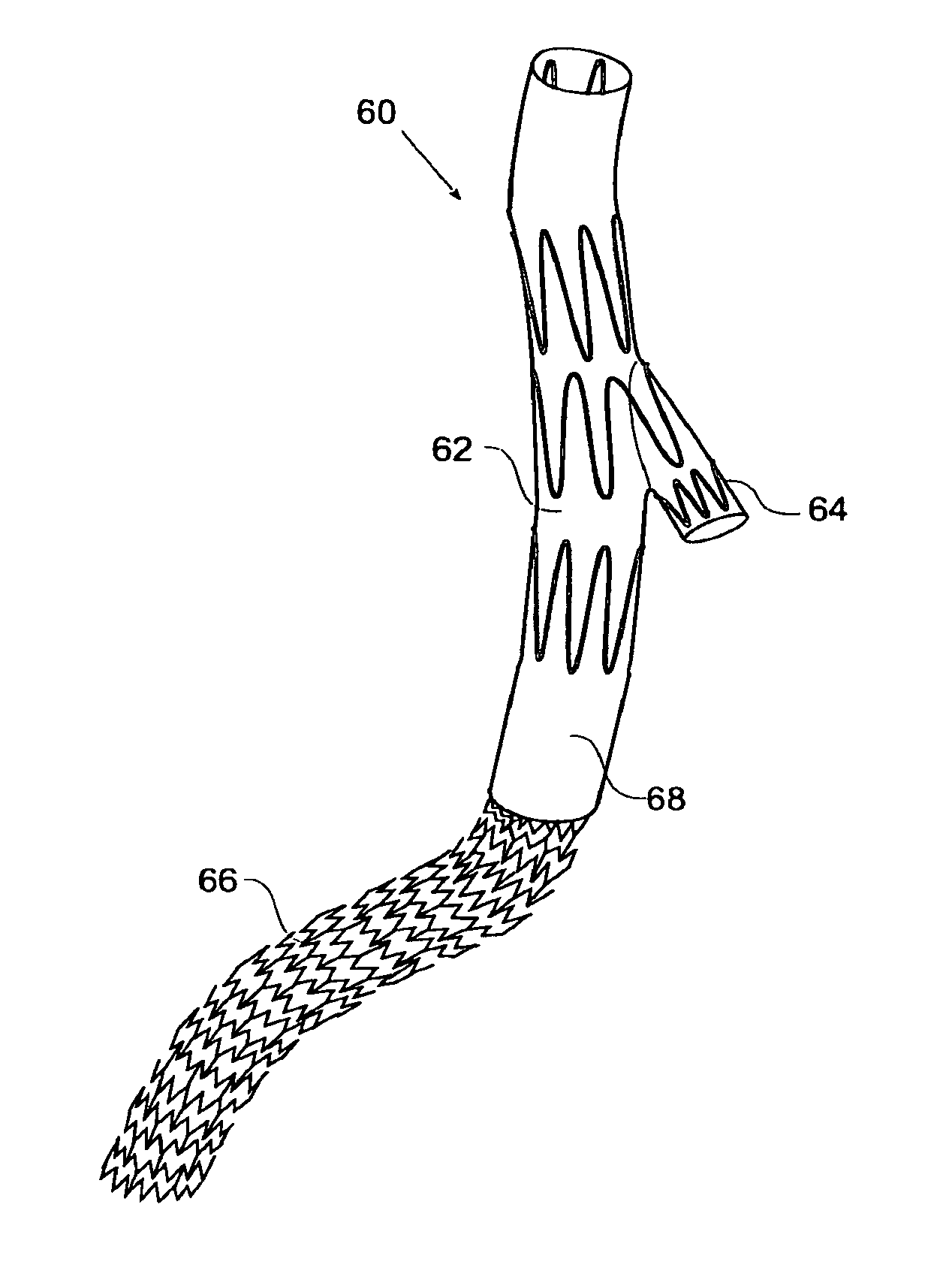
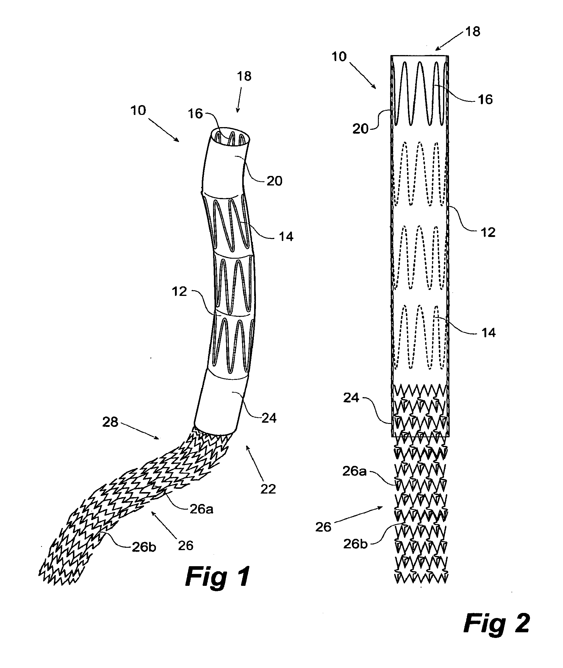
[0027]Now, looking more closely at the drawings and in particular FIGS. 1 and 2, a first embodiment of stent graft according to the present invention is described.

[0028]In this embodiment, the stent graft leg extension 10 comprises a tubular body 12 of a biocompatible graft material with a number of zig-zag Gianturco stents 14 on its outer surface between its ends and an inner zig-zag Gianturco stent 16 at the proximal end 18. On the outside of the proximal end, the biocompatible graft material provides a sealing surface 20. At the distal end 22 of the tubular body is another sealing surface 24 and extending from the end 22 is a tubular self-expanding stent 26. The tubular zig-zag stent 26 comprises circumferential zig-zag portions 26a with flexible longitudinal links 26b between the circumferential portions.

[0029]As can be seen particularly in FIG. 2, which shows a longitudinal cross-section of the stent graft shown in FIG. 1, the tubular stent 26 extends within the tubular body 12...


PUM


Abstract

A stent graft leg extension (10) to extend from a bifurcated aortic stent graft into an iliac artery. The stent graft has a tubular body. (12) of a biocompatible graft material and a plurality of self-expanding stents (14) joined to and supporting the tubular body. An uncovered tubular self-expanding stent assembly (26) extends from a first end of the tubular body and is fastened thereto. The uncovered tubular self-expanding stent assembly (26) provides a smooth transition from the leg extension into the iliac artery to reduce the chance of kinks causing problems in the leg extension.

Description

TECHNICAL FIELD[0001]This invention relates to a medical device and more particularly to a medical device for use in relation to endovascular surgery.BACKGROUND OF THE INVENTION[0002]Bifurcated stent grafts are well known for treating abdominal aortic aneurysms. Such stent grafts typically include a tubular body which extends in the aorta towards the renal arteries of a patient and a bifurcation. The bifurcation usually has a shorter leg and a longer leg. Once the bifurcated graft is deployed, an extension leg is provided to extend down one iliac artery from the shorter leg, with the longer leg extending down the other iliac artery.[0003]There can be problems with such stent grafts, however, for example in cases in which the iliac artery is extremely convoluted, as is often the case with older patients. The extension leg provided to extend down one iliac artery from the shorter leg of the bifurcated aortic stent graft can be kinked in the convoluted region, thereby blocking off bloo...

Claims


Application Information

Patent Timeline
Patent Type & Authority Applications(United States)
IPC IPC(8): A61F2/06A61F2/82
CPCA61F2/07A61F2/89A61F2002/075A61F2002/067
Inventor CHUTER, TIMOTHY A.M.GREENBERG, ROY K.
Owner THE CLEVELAND CLINIC FOUND
Learn More