
Smoke detecting apparatus

a detection apparatus and smoke technology, applied in the field of smoke detection apparatus, can solve the problems of difficult luminance difference setting, low detection efficiency, false detection of smoke, etc., and achieve the effect of suppressing the disturbance effect and high detection efficiency

Inactive Publication Date: 2010-04-22
UNIVERSITY OF TOKUSHIMA +1
View PDF10 Cites 19 Cited by
  • Summary
  • Abstract
  • Description
  • Claims
  • Application Information

AI Technical Summary

Benefits of technology

[0015]The present invention has been made to solve the above-mentioned problems, and an object of the present invention is therefore to provide a smoke detecting apparatus capable of detecting smoke at high sensitivity while suppressing the effect of disturbance.
[0016]Another object of the present invention is to provide a smoke detecting apparatus which avoids false detection due to the effect of disturbance without limiting the range that may be monitored.
[0020]Further, according to the present invention, there may also be obtained the smoke detecting apparatus which avoids false detection due to the effect of disturbance without limiting the range that may be monitored, by performing smoke detection using a reference judgment value having a desired detection sensitivity for each region depending on the object to be monitored.

Problems solved by technology

However, the related art has the following problems.
However, there has been a problem in that, for example, when the captured image changes due to an effect of a change in surrounding illumination condition or the like, a portion with no occurrence of smoke may be falsely detected as smoke.
Therefore, simply determining the differential image alone may not allow smoke detection at high sensitivity because the threshold setting for the luminance difference is difficult.
However, the location to be monitored may not always have such good conditions.
Moving objects such as people may come and go in a monitoring range in one location, or the sunshine condition may change with time in another location, to thereby render a partial area of the monitoring range unsuitable for monitoring.
It is also possible to divide the image into a matrix of regions of a predetermined size and mask the area (region) unsuitable for monitoring to be excluded from the smoke detection, but the masking results in limiting the range that may be monitored.

Method used


Image

  • Smoke detecting apparatus
  • Smoke detecting apparatus
  • Smoke detecting apparatus

Examples


first embodiment

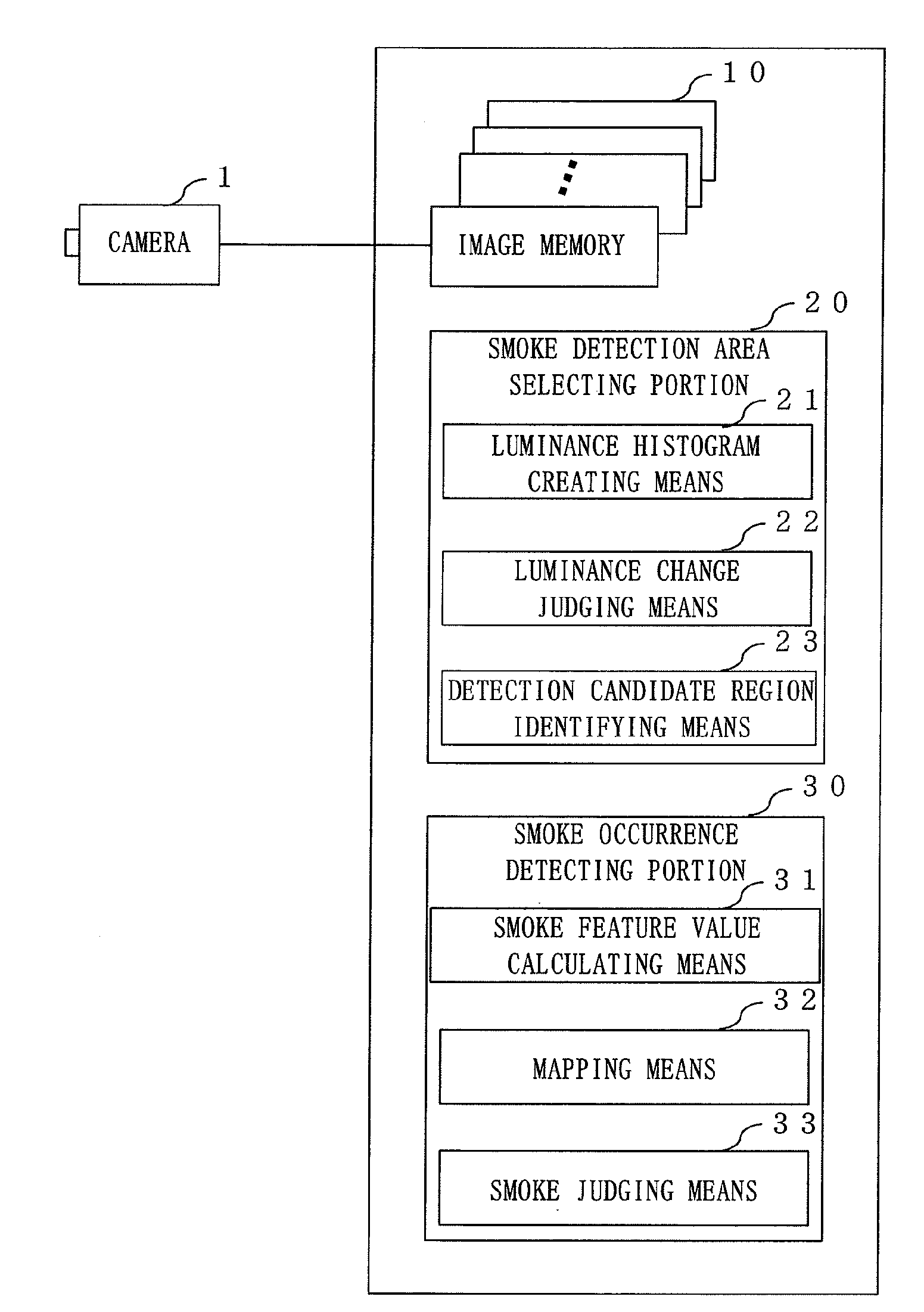
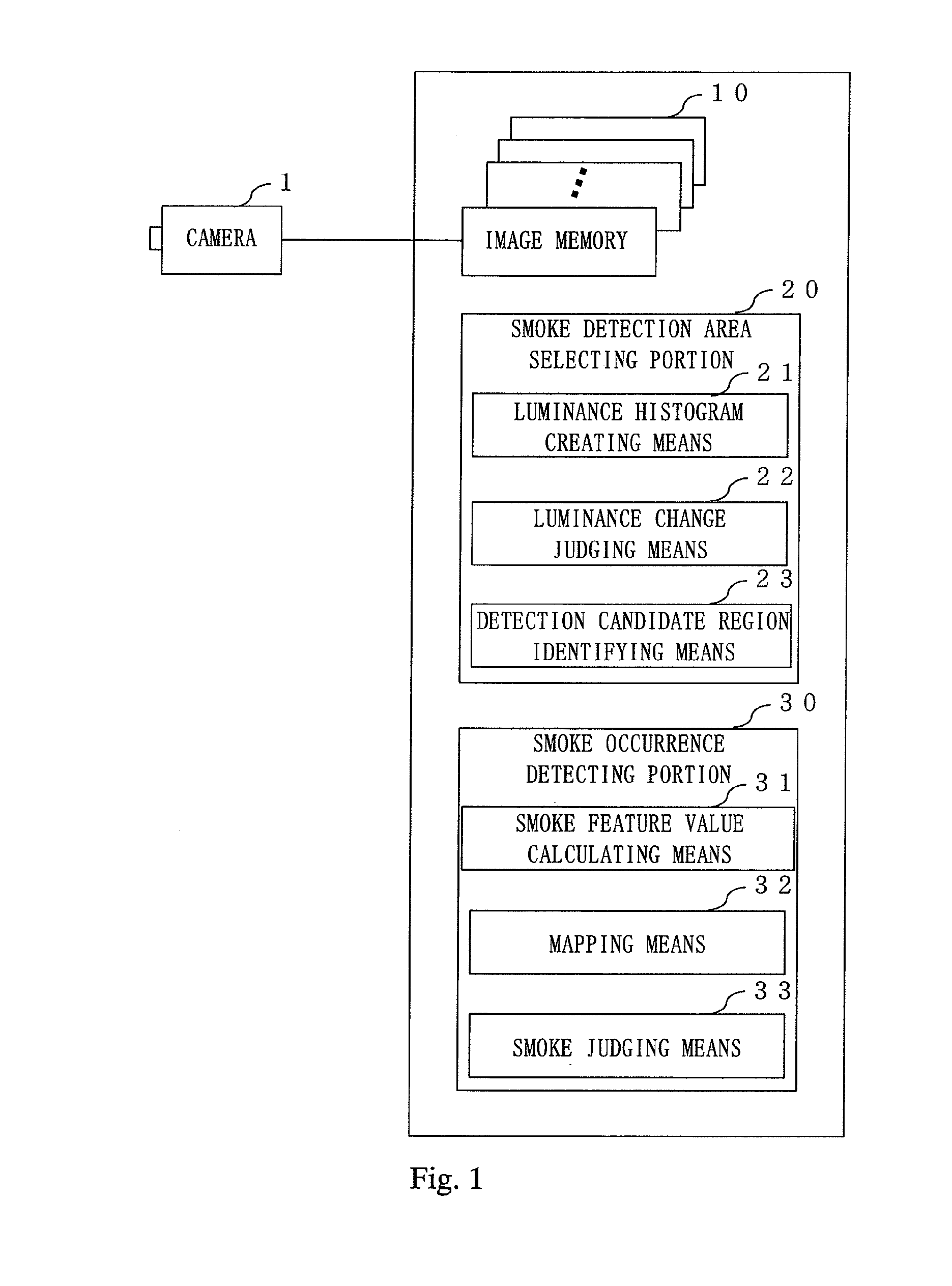
[0034]FIG. 1 is a configuration diagram of a smoke detecting apparatus according to a first embodiment of the present invention. The smoke detecting apparatus according to the first embodiment of the present invention includes an image memory 10, a smoke detection area selecting portion 20, and a smoke occurrence detecting portion 30. The image memory 10 is configured as an image memory for a plurality of frames so that images captured by a camera 1 may be stored over a past predetermined period as time-series data.

[0035]The smoke detection area selecting portion 20 includes luminance histogram creating means 21, luminance change judging means 22, and detection candidate region identifying means 23. The smoke detection area selecting portion 20 has a function of identifying areas to be subjected to smoke detection as smoke detection candidate regions based on the images captured by the camera 1 and stored in the image memory 10 over the past predetermined period.

[0036]The smoke occu...

second embodiment

[0093]FIG. 7 is a configuration diagram of the smoke detecting apparatus according to the second embodiment of the present invention. The smoke detecting apparatus according to the second embodiment of the present invention includes an image memory 10, a storage portion 15, smoke feature value calculating means 31, region-to-region sensitivity setting means 40, and smoke judging means 33. The image memory 10 is configured as an image memory for a plurality of frames so that images captured by a camera 1 may be stored over a past predetermined period as time-series data.

[0094]The image to be monitored is previously divided into a plurality of predetermined regions to set the plurality of regions in the image. FIG. 8 is an explanatory diagram of a regional segmentation of the image to be monitored according to the second embodiment of the present invention. FIG. 8 illustrates a case where the image to be monitored is previously divided into 20 regions to form a matrix of 4 rows and 5 ...

third embodiment

[0122]As described above, the second embodiment describes the case where a desired detection sensitivity is manually set (that is, statically set) for each region in advance depending on the object to be monitored. In contrast, a third embodiment of the present invention describes a case where presence or absence of an effect of disturbance such as a moving object and an illumination change is judged based on an analysis result of a current captured image, and the detection sensitivity is set dynamically.

[0123]FIG. 10 is a configuration diagram illustrating a smoke detecting apparatus according to the third embodiment of the present invention. Compared to the configuration of FIG. 7 illustrating the smoke detecting apparatus of the second embodiment described above, the configuration of FIG. 10 illustrating the smoke detecting apparatus of the third embodiment of the present invention is different in that disturbance occurrence detecting means 60 is newly added. Therefore, a functio...


PUM


Abstract

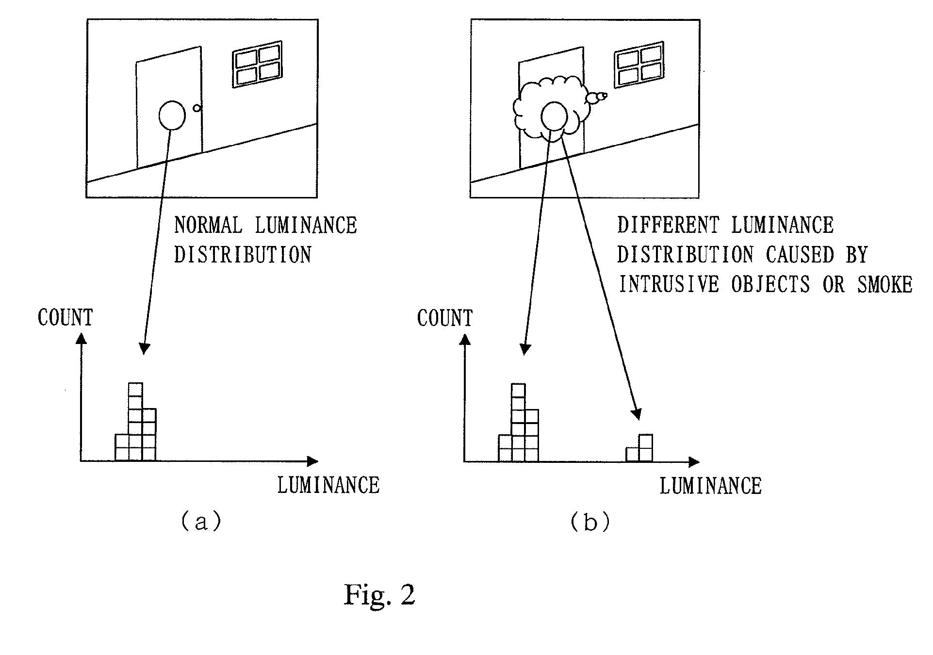
Provided is a smoke detecting apparatus capable of detecting occurrence of smoke at high sensitivity while suppressing an effect of disturbance. The smoke detecting apparatus for detecting occurrence of smoke by subjecting an image captured by a monitoring camera to image processing includes: an image memory (10) for storing a plurality of images captured by the monitoring camera in a time series; and a smoke detection area selecting portion (20) for calculating a luminance histogram of the same pixel for each predetermined pixel a plurality of times in a past predetermined period based on the plurality of images stored in the image memory (10), detecting presence or absence of a luminance value that has been newly generated due to occurrence of one of an intrusive object and smoke based on the luminance histogram, and identifying candidate regions to be subjected to the image processing.

Description

BACKGROUND OF THE INVENTION[0001]1. Field of the Invention[0002]The present invention relates to a smoke detecting apparatus for detecting occurrence of smoke by subjecting an image captured by a monitoring camera to image processing, and more particularly, to a smoke detecting apparatus capable of avoiding false detection and detection failure due to an effect of disturbance.[0003]2. Description of the Related Art[0004]Early detection of fire or smoke is very important in view of early fire control upon occurrence of a fire, and in view of preventing trapping in a fire accident. Therefore, in the field of smoke detecting apparatuses, studies have been conducted for early smoke detection by subjecting an image captured by a monitoring camera to image processing.[0005]As an example, there has been known a smoke detecting apparatus for detecting smoke by installing a camera in a tunnel or the like and subjecting an image captured by the camera to image processing. In the image process...

Claims


Application Information

Patent Timeline
Patent Type & Authority Applications(United States)
IPC IPC(8): G06K9/00
CPCG08B17/125
Inventor YAMAGISHI, TAKATOSHINAKANO, KAZUHISATERADA, KENJI
Owner UNIVERSITY OF TOKUSHIMA
Learn More