Wireless tire pressure monitor system

a tire pressure monitor and wireless technology, applied in the direction of tyre measurement, antenna details, antennas, etc., can solve the problems of low hit ratio of conventional tpms, inability to detect abnormal tire pressure, and inability to receive wrong signals or misread signals, etc., to achieve high hit ratio

Inactive Publication Date: 2010-04-22
TUNG THIH ELECTRONICS
View PDF9 Cites 3 Cited by
  • Summary
  • Abstract
  • Description
  • Claims
  • Application Information

AI Technical Summary

Benefits of technology

[0010]The main objective of the invention is to provide a wireless tire pressure monitor system having high hit ratio for receiving wireless signals. The wireless tire pressure monitor system can inform drivers of abnormal tire pressure precisely and timely.
[0011]The wireless tire pressure monitor system in accordance with the present invention comprises multiple pressure sensors and at least one receiving module. The pressure sensors detect tire pressures and transmit wireless signals representing the tire pressure. The at least one receiving module is mounted on a chassis of a vehicle at a geometric center of the pressure sensors and has an annular antenna. The annular antenna receives wireless signals from the pressure sensors equally. Therefore, the present invention avoids external electromagnetic interference and has a high hit ratio for receiving wireless signals.

Problems solved by technology

Furthermore, being located adjacent to other devices in the vehicle such as GPS, radios and the like, the receiving module (60) of the conventional TPMS may receive a wrong signal or misread the signal due to electromagnetic interference.
Therefore, the conventional TPMS suffers from the low hit ratio, and the conventional TPMS may mis-detect abnormal tire pressures.
Mis-detection of abnormal tire pressures may cause a driver to continue driving despite being at risk.

Method used


Image

  • Wireless tire pressure monitor system
  • Wireless tire pressure monitor system
  • Wireless tire pressure monitor system

Examples


Embodiment Construction

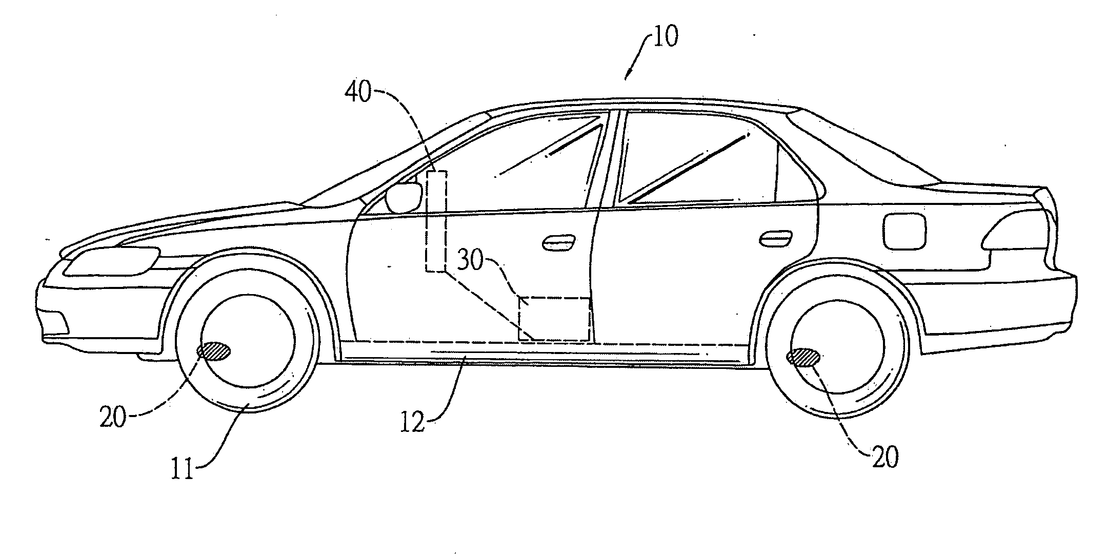
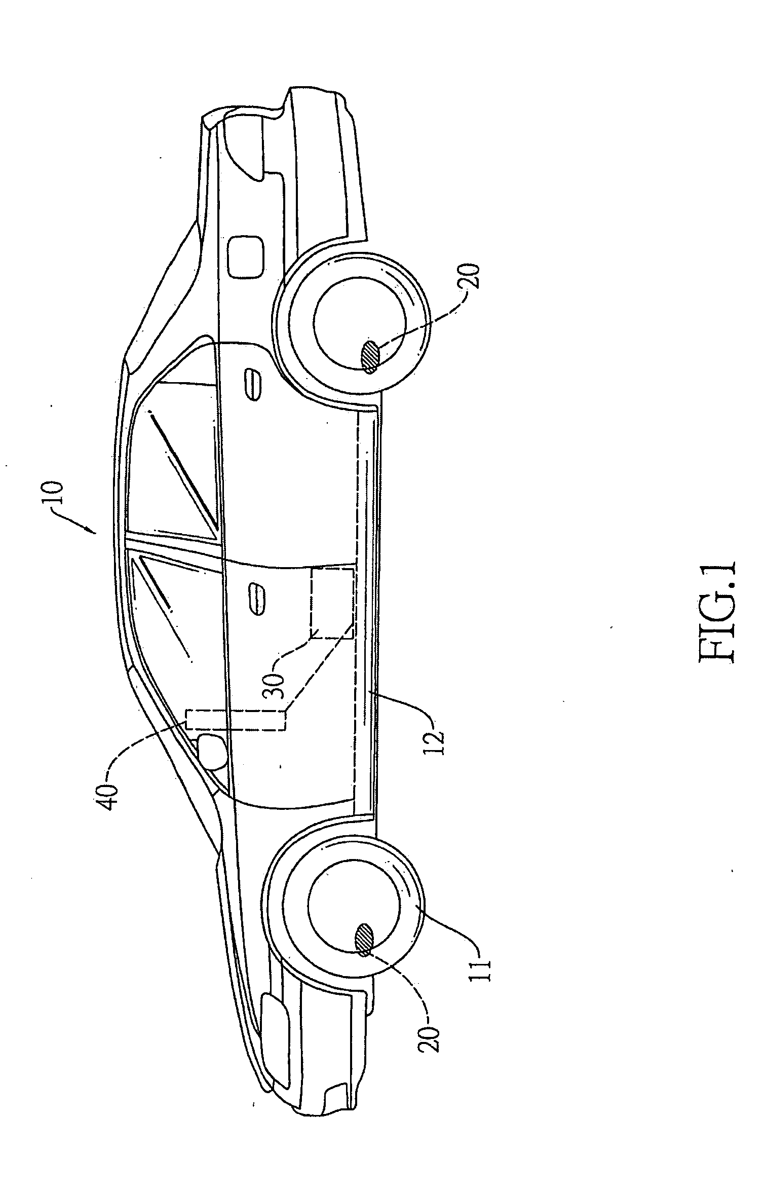
[0019]With reference to FIGS. 1 and 2, a wireless tire pressure monitor system in accordance with the present invention is mounted in a vehicle (10) and comprises multiple pressure sensors (20) and at least one receiving module (30).

[0020]The pressure sensors (20) are mounted respectively in tires (11) of the vehicle (10) to detect tire pressures, and each pressure sensor (20) transmits a wireless signal representing the tire pressure of the corresponding tire (11).

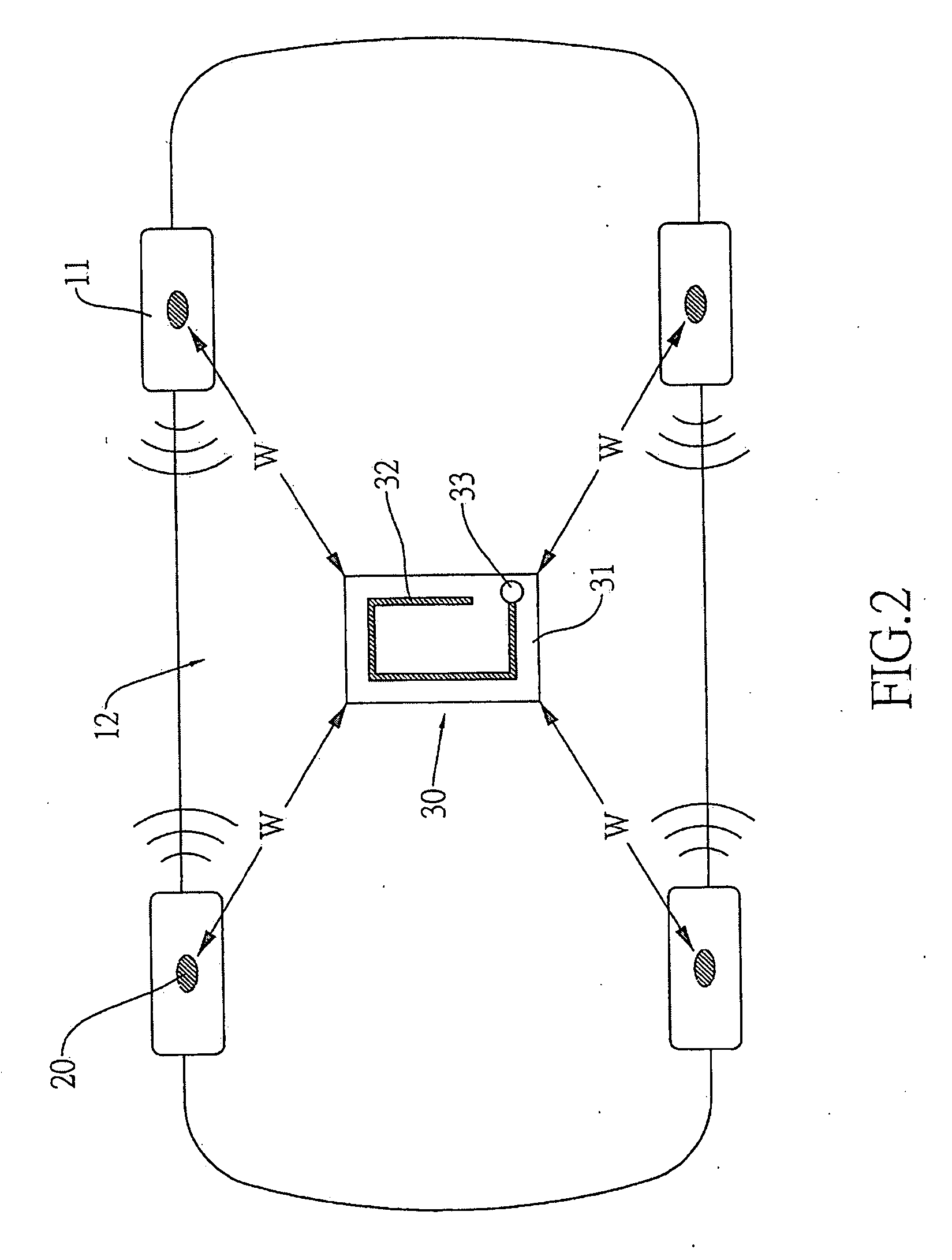
[0021]The receiving module (30) is mounted on a chassis (12) of the vehicle (10) at a geometric center of the pressure sensors (20) so distances (W) between the receiving module (30) and the pressure sensors (20) are the same as each other. Because the receiving module (30) is mounted on a chassis (12) of the vehicle (10), the distances (W) between the receiving module (30) and the corresponding pressure sensors (20) are as short as possible when the distances (W) are the same as each other.

[0022]Furthermore, the receivin...


PUM


Abstract

A wireless tire pressure monitor system has multiple pressure sensors and at least one receiving module. The pressure sensors detect tire pressures and transmit wireless signals representing the tire pressure. The at least one receiving module is mounted on a chassis of a vehicle at a geometric center of the pressure sensors and has an annular antenna. The annular antenna receives wireless signals from the pressure sensors equally. Therefore, because distances between the receiving module and the pressure sensors are the same and the annular antenna has good receiving characteristics, the wireless tire pressure monitor system has a high hit ratio for receiving wireless signals.

Description

BACKGROUND OF THE INVENTION[0001]1. Field of the Invention[0002]The present invention relates to a wireless tire pressure monitor system, and more particularly to a wireless tire pressure monitor system having high hit ratio for receiving wireless signals.[0003]2. Description of Related Art[0004]Many new designs are invented for vehicles to improve aesthetics, efficiency and safety, such as vehicle braking detectors and tire pressure monitor systems (TPMS) or the like. The TPMS detects whether tire pressure is normal.[0005]With reference to FIG. 6, a conventional TPMS is mounted in a vehicle having tires and comprises multiple pressure sensors (50), a monitor (70) and a receiving module (60). The pressure sensors (50) are mounted respectively in the tires to detect tire pressures and transmit wireless signals representing the tire pressures. The monitor (70) is mounted in the vehicle, near a driver's seat. The receiving module (60) is mounted adjacent to and connected to the monitor...

Claims


Application Information

Patent Timeline
IPC IPC(8): B60C23/00
CPCB60C23/008H01Q1/2241B60C23/0444B60C23/0408
Inventor CHEN, SHIN-CHUNGCHEN, SEN-JUNGYANG, SHEN-SHENG
Owner TUNG THIH ELECTRONICS
Why Eureka
Try Eureka